- Catalogs
- Beijing DWIN Technology Co., Ltd.
- ET121S0M-N11
- Company
- Products
- Catalogs
- News & Trends
- Exhibitions
ET121S0M-N11
1 /25Pages

ET121S0M-N11
1 /25Pages
Catalog excerpts
PROPRIETARY NOTE THIS SPECIFICATION IS THE PROPERTY OF BOE HF AND SHALL NOT BE REPRODUCED OR COPIED WITHOUT THE WRITTEN PERMISSION OF BOE HF AND MUST BE RETURNED TO BOE HF UPON ITS REQUEST SPEC. NUMBER PRODUCT GROUP ISSUE DATE B3 ET121S0M-N11 Product Specification Rev.PO BUYER
Open the catalog to page 1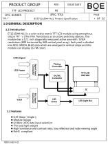
PRODUCT GROUP TFT- LCD PRODUCT ISSUE DATE SPEC. TITLE SPEC. NUMBER 1.0 GENERAL DESCRIPTION 1.1 Introduction ET121S0M-N11 is a color active matrix TFT LCD module using amorphous silicon TFT‘s (Thin Film Transistors) as an active switching devices. This module has a 12.1 inch diagonally measured active area with SVGA resolutions (800 horizontal by 600 vertical pixel array). Each pixel is divided into RED, GREEN, BLUE dots which are arranged in vertical stripe and this module can display 16.7M colors. LVDS Signal Signal Input Connector Timing Controller DC/DC Converter 1.2 Features 0.5T Glass(Single);...
Open the catalog to page 4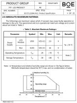
Note : 1) Temperature and relative humidity range are shown in the figure below. Wet bulb temperature should be 39 °C max. and no condensation of water.
Open the catalog to page 6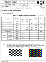
Notes : 1. The supply voltage is measured and specified at the interface connector of LCM. The current draw and power consumption specified is for VBAT=3.8V, Frame rate fV=60Hz and Clock frequency = 156.8MHz. Test Pattern of power supply current a) Typ : Mosaic 8 x 6 Pattern(L0/L255) b) Max : skip 1H1V dot(L0/L255) 2. The duration of rush current is about 2ms and rising time of Power Input is 1ms(min)
Open the catalog to page 7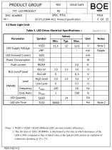
ISSUE DATE SPEC. TITLE B3 ET121S0M-N11 Product Specification Table 5. LED Driver Electrical Specifications > [Ta =25+2 c] Notes: 1. PLED = VLED x ILED (Without LED converter transfer efficiency) 2. The life time of LED, 30,000Hrs, is determined as the time at which luminance of the LED is 50% compared to that of initial value at the typical LED current on condition of continuous operating at 25 ± 2°C.
Open the catalog to page 8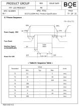
ISSUE DATE SPEC. TITLE B3 ET121S0M-N11 Product Specification Tcon Reset Interface Signal (LVDS/MIPI/eDP) < Table15. Sequence Table > Parameter
Open the catalog to page 11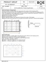
NoteirLuminance measurement The test condition is at ILED=20mA and measured on the surface of LCD module at 25°C. •The data are measured after LEDs are lighted on for more than 5 minutes and LCM displays are fully white. The brightness is the average value of 9 measured spots. Measurement equipment CS2000 or si milar equipments(Field of view:1deg,Distance:50cm) • Measuring surroundings: Dark room. • Measuring temperature: Ta=25C. •Adjust operating voltage to get optimum contrast at the center of the display. • Measured value at the center point of LCD panel must be after more than 5 minutes while...
Open the catalog to page 13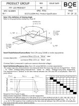
PRODUCT GROUP TFT- LCD PRODUCT ISSUE DATE SPEC. TITLE SPEC. NUMBER Note 3:The definition of Viewing Angle Refer to the graph below marked by θ and Ф. Note4:ThedefinitionofContrastRatio (Test LCM using CS2000 or similar equipments): Contrast Ratio(CR)= Luminance When LCD is at “White” state Luminance When LCD is at “Black” state (Contrast Ratio is measured in optimum common electrode voltage) Note5:DefinitionofResponse time.(Test LCD using DMS501 or similar equipments): The output sign also photo detector are measured when the input sign also are changed from “black ” to “white”(Voltage falling...
Open the catalog to page 14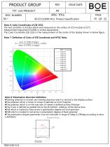
SPEC. TITLE B3 ET121S0M-N11 Product Specification PAGE 15 OF 25 Note 6: Color Coordinates of CIE 1931 The test condition is at ILED=20mA and measured on the surface of LCD module at 25°C. Measurement equipment:CS2000 or similar equipments The Color Coordinate (CIE 1931) is the measurement of the center of the display shown in below figure. Note 7: Definition of Color of CIE Coordinate and NTSC Ratio. Note 8: Polarization Direction Definition •Viewing direction is normal user viewing direction which is vertical to the display surface •The polarizer which is closer to viewer is defined as Front...
Open the catalog to page 15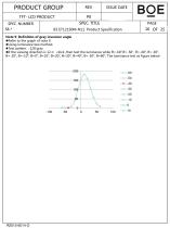
Note 9: Definition of gray inversion angle • Refer to the graph of note 9. • Using luminance test method. •Test pattern : 128 gray •If the viewing direction is 12 o'clock ,then test the luminance while 0=-60°,0=-50°, 0=-40°, 0=-30°, 0=-20°, 0=-10°, 0=0°, 0=10°, 0=20°, 0=30°, 0=40°, 0=-50°, 0=60°. The luminance test as figure below:
Open the catalog to page 16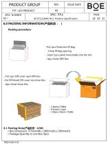
PRODUCT GROUP SPEC. TITLE SPEC. NUMBER ISSUE DATE 6.0 PACKING INFORMATION(产品形态: ) Packing procedure: -.Put 1pcs Panel into PE Bag Crimp PE Bag opening -. Insert 1pcs panel horizontally into the slot -. 8pcs Panel /EPE Box -. Put 1pcs EPE cover upon EPE box -.Put EPE Box& EPE cover into Inner Box -. 8pcs Panel /Inner Box -. 3 layers/ Pallet -. 8 boxes/ Layer -. 192pcs Panel / Pallet 6.1 Packing Note(产品形态:LCM) Box Dimension: 375mm(W) x 280mm(D) x 290mm(H) Package Quantity in one Box: 8pcs
Open the catalog to page 18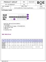
ISSUE DATE SPEC. TITLE B3 ET121S0M-N11 Product Specification 7.0 Product Label Label Size: 48mmx12mmx0.08mm, 44-9231007 1. FG-CODE First 12 digits : ET121S0M-N11
Open the catalog to page 20
8.1 Mounting Method • The panel of the LCD consists of two thin glasses with polarizers which easily get damaged. So extreme care should be taken when handling the LCD. • Excessive stress or pressure on the glass of the LCD should be avoided. Care must be taken to insure that no torsional or compressive forces are applied to the LCD unit when it is mounted. • If the customer's set presses the main parts of the LCD, the LCD may show the abnormal display. But this phenomenon does not mean the malfunction of the LCD and should be pressed by the way of mutual agreement. • To determine the optimum...
Open the catalog to page 21
8.3 Caution Against Static Charge • The LCD modules use C-MOS LSI drivers, so customers are recommended that any unused input terminal would be connected to Vdd or Vss, do not input any signals before power is turn on, and ground you body, work/assembly area, assembly equipments to protect against static electricity. • Remove the protective film slowly, keeping the removing direction approximate 30-degree not vertical from panel surface, If possible, under ESD control device like ion blower, and the humidity of working room should be kept over 50%RH to reduce the risk of static charge. • Avoid...
Open the catalog to page 22All Beijing DWIN Technology Co., Ltd. catalogs and technical brochures
 DMG19108K133_05W
19 Pages
 DMG10768K121_03W
17 Pages
 DMG12800K121_03W
19 Pages
 DMG10768K104_03W
19 Pages
 DMG12800K101_03W
18 Pages
 DMG10600K101_03W
19 Pages
 DMG10768K097_03W
19 Pages
 DMG12800K080_03W
19 Pages
 DMG10768K080_03W
19 Pages
 DMG80600K080_03W
19 Pages
 DMG12800K070_03W
19 Pages
 DMG10600K070_03W
19 Pages
 DMG80480K070_03W
19 Pages
 DMG64480K057_03W
17 Pages
 DMG85480K050_03W
19 Pages
 DMG80480K050_03W
19 Pages
 DMG80480K043_03W
18 Pages
 DMG80480K035_03W
18 Pages
 DMG64480K035_03W
17 Pages
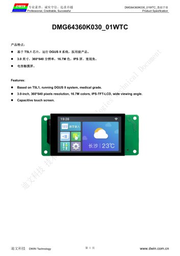 DMG64360K030_01W
18 Pages
 DMG48320T035_15W
15 Pages
 DMG10768T150_01W
14 Pages
 DMG10768T121_01W
14 Pages
 DMG80600T121_01W
13 Pages
 DMG10768T104_09W
14 Pages
 DMG10768T104_01W
14 Pages
 DMG80600T104_01W
14 Pages
 DMG12800T101_01W
14 Pages
 DMG10600T101_09W
14 Pages
 DMG10600T101_01W
14 Pages
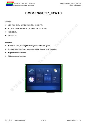 DMG10768T097_01W
14 Pages
 DMG19480T088_01W
14 Pages
 DMG10768T080_01W
14 Pages
 DMG12800T080_01W
14 Pages
 DMG80600T080_09W
14 Pages
 DMG80600T080_02W
16 Pages
 DMG48270F043_01W
18 Pages
 DMG12800T070_01W
14 Pages
 DMG10600T070_09W
14 Pages
 DMG10600T070_01W
14 Pages
 DMG80480T070_09W
16 Pages
 DMG80480T070_05W
14 Pages
 DMG64480T057_01W
14 Pages
 DMG12720T050_01W
14 Pages
 DMG80480T050_09W
14 Pages
 DMG80480T050_02W
14 Pages
 DMG80480T043_09W
14 Pages
 DMG80480T043_01W
14 Pages
 DMT12800T101_36WTC
6 Pages
 DMT80480T050_36WTC
7 Pages
 DMT10600T070_36WTR
7 Pages
 DMT10600T070_36WTC
7 Pages
 DMT10600T101_36WTC
7 Pages
 DMG80480T040_01W
14 Pages
 DMG48480T040_01W
14 Pages
 DMG80480T035_01W
14 Pages
 DMG64480T035_01W
14 Pages
 DMG64360T030_01W
14 Pages
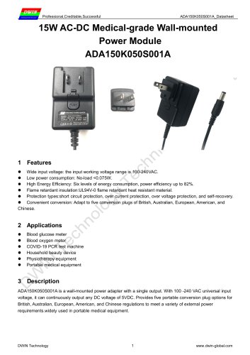 ADA150K050S001A
7 Pages
 ADA360K240S001A
8 Pages
 LN80480T070IA9098
23 Pages
 TC040C14 U(W) 04
8 Pages
 TC041C11 U(W) 04
7 Pages
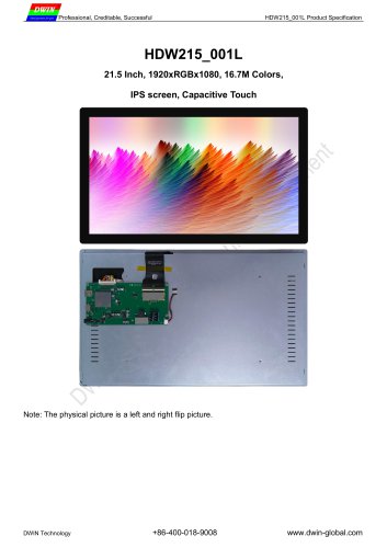 HDW215_001L 2025
4 Pages
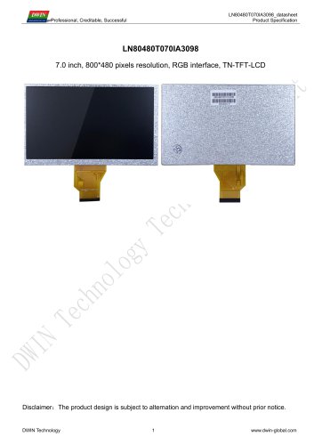 LN80480T070IA3098
23 Pages
 HR4 8545 10.4
12 Pages
 HR4 8537 8.0
12 Pages
 YF07002
12 Pages
 YF04303
12 Pages
 TPC156T0001G01V1
14 Pages
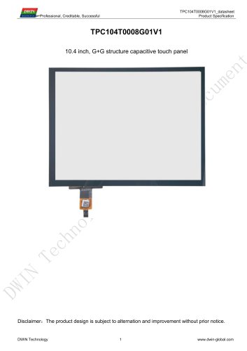 TPC104T0008G01V1
13 Pages
 TPC101T0001G01V1
14 Pages
 TPC097T0002G01V1
14 Pages
 TPC080Z0009G01V1
14 Pages
 TPC070T0004G01V3
14 Pages
 TPC070T0050G01V1
13 Pages
 GME0831B
14 Pages
 TPC043Z0001G01V1
13 Pages
 TPC035C0004G01V1
14 Pages
 TP024Z0001A
14 Pages
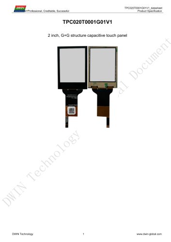 TPC020T0001G01V1
14 Pages
 LI12720T050TA3098
28 Pages
 LN80480T050IA9098
23 Pages
 LN80480T050IA4098
22 Pages
 LI80480C050HA9098
22 Pages
 LI48800T043TC3098
23 Pages
 LI48800T043TD3098
23 Pages
 LN48272T043IB3598
22 Pages
 LI72720T041TA3598
26 Pages
 LI48320T035IB3098
23 Pages
 LI48480T028BA3098
23 Pages
 LN32240T028SA3598
23 Pages
 LN32240T024SA3098
23 Pages
 LI24320T020SA3598
23 Pages
 LI24240T015HA5598
23 Pages
 LI24240C013HA2098
23 Pages
 ADA100K050S001A
7 Pages
 ADA360K240S001B
10 Pages
 ADA360K120S001A
8 Pages
 ADA360K120S001B
10 Pages
 TC040C11 U(W) 04
7 Pages
 TC040C15W04
13 Pages
 TC041C12 U(W) 00
10 Pages
 TC070C22 U(W) 00
8 Pages
 TC040C12U/W00
7 Pages
 TC040C17W00
9 Pages
 HDW080_A5001L
5 Pages
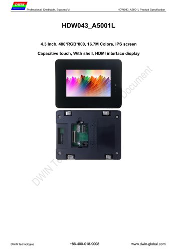 HDW043_A5001L
6 Pages
 HDW156_001L
4 Pages
 HDW104_001RTD
5 Pages
 HDW101_007L
5 Pages
 HDW070_A5001L
6 Pages
 DMG10768T150_40WTC
6 Pages
 DMG10600C101_40WTC
6 Pages
 DMG12800T070_40WTC
6 Pages
 DMG12800C070_40WTC
6 Pages
 DMG80480T050_40WTC
6 Pages
 DMG19108C156_32WTC
6 Pages
 DMG10768T150_32WTC
6 Pages
 DMG10600C101_32WTC
6 Pages
 DMG12800T070_32WTC
6 Pages
 DMG12800C070_32WTC
6 Pages
 DMG80480T050_32WTC
6 Pages
 DWIN Touch Panel Catalog
8 Pages
 DWIN TFT LCD Catalog
24 Pages
 DMG10600C101_15WTR
17 Pages
 DMG80480C070_15WTR
17 Pages
 DMG48270C043_15WTR
15 Pages
 DMG48480C021_13WTC
12 Pages
 DMG24240C015_13WN
10 Pages
 DMG24240C013_13WN
10 Pages
 DMG19108C215_05W
13 Pages
 DMG19108C185_05W
13 Pages
 DMG19108C173_05W
13 Pages
 DMG19108C156_05W
13 Pages
 DMG19108C140_05W
13 Pages
 DMG19108C133_05W
13 Pages
 DMG19108C116_05W
13 Pages
 DMG13768C185_03W
13 Pages
 DMG13768C156_03W
13 Pages
 DMG10768C150_03W
13 Pages
 DMG12800C121_02W
13 Pages
 DMG80600C121_03W
13 Pages
 DMG10768C104_03W
13 Pages
 DMG80600C104_03W
13 Pages
 DMG10600C101_03WTC
15 Pages
 DMG10768C097_03WTC
14 Pages
 DMG12800C070_03W
13 Pages
 DMG10600C070_03W
15 Pages
 DMG80480C070_04W
13 Pages
 DMG80480C070_03W
15 Pages
 DMG48270C043_05W
13 Pages
 DMG48270C043_04W
14 Pages
 DMG48270C043_03W
14 Pages
 DMG72720C041_03W
13 Pages
 DMG48480C040_03W
13 Pages
 DMG80480C040_03W
14 Pages
 DMG96240C037_03W
14 Pages
 DMG48320C035_03W
14 Pages
 DMG32240C035_03W
14 Pages
 DMG48480C028_03W
13 Pages
 DMG32240C028_03W
13 Pages
 DMG32240C024_03W
14 Pages
 DMG48480C021_03W
12 Pages
 DMG32240C020_03W
13 Pages
 DMG24240C015_03W
13 Pages
 DMG24240C013_03W
13 Pages
 HDMI+LVDS Catalog
38 Pages
 IOT Catalog
16 Pages
 SYSTEM SCREEN CATALOG
46 Pages
 Video screen catalog
43 Pages
 COF Screen Catalog
33 Pages
 DWIN UART Catalog 2024
82 Pages
 DMG85480C050_03WTR
12 Pages
 DMG48270C043_03WTC
12 Pages
 DMG48270C043_03WTR
12 Pages
 DMG48270C043_03WN
12 Pages
 DMG80480C043_01WTC
12 Pages
 DMG80480C043_01WTR
12 Pages
 DMG80480C043_01WN
12 Pages
 DMG80480C043_02WTC
12 Pages
 DMG80480C043_02WTR
12 Pages
 DMG80480C043_02WN
12 Pages
 DMG80480C050_03WTC
12 Pages
 DMG80480C050_03WTR
12 Pages
 DMG80480C050_03WN
12 Pages
 DMG80600C080_03W
12 Pages
 DMG10768C080_03W
12 Pages
 DMG10600C101_03W
12 Pages
 DMG10768C097_03W
12 Pages
 DMG19480C088_03W
12 Pages
 DMG10768C104_03W
12 Pages
 DMG10768C150_03W
12 Pages
 DMG12800C121_02W
12 Pages
 DMG80600C104_03W
12 Pages
 DMG80600C121_03W
12 Pages
 DMG12800T101_01WTR Datasheet
12 Pages
 DMG12800T101_01WTC Datasheet
12 Pages
 DMG12800T101_01WN Datasheet
12 Pages
 DMG64480C056_03WTC
12 Pages
 DMG64480C056_03WTR
12 Pages
 DMG64480C056_03WN
12 Pages
 DMG80480T070_A5WTR Datasheet
13 Pages
 DMG80480T043_A5WTR Datasheet
18 Pages
 DMG80480F070_01WTR Datasheet
18 Pages
 DMG48270F043_01WTR
18 Pages
 DMG48480F040_01WTC
21 Pages
 DMG48320F035_01WTC Datasheet
21 Pages
 DMG80480T035_01WTR
12 Pages
 HDW215_001L
4 Pages
 HDW104_001L
3 Pages
 HDW101_001L
4 Pages
 HDW050_003L
4 Pages
 HDW043_001L
4 Pages
 LI48800T043TA3004
15 Pages
 LQ035NC111_V03_20101230
29 Pages
 TM041XDHC02-00-YGT1-02
1 Page
 EV121X0M-N10
36 Pages
 EV101WXM-N10
34 Pages
 LN80600T104TB3001
19 Pages
 LN80600T104IA4501
17 Pages
 LN80600T080IA4001
14 Pages
 LN80480T050IC4004
17 Pages
 LI85480T050HD4504
18 Pages
 LI10768T104HB3001
18 Pages
 LI10600T070HA3004
19 Pages
 HDW070_007L
3 Pages
 LI48800T043TB3004
14 Pages
 LQ035NC111
29 Pages
 TN028C11U04
8 Pages
 TC070C12U00
6 Pages
 TC043C12U00
3 Pages
 TC041C11W04
4 Pages
 TC040C11U04
4 Pages


Archived catalogs
 DMG12800T070_33WTC
4 Pages
- DC power supply
- AC/DC power supply
- LCD screen
- Monitor with touchscreen
- Industrial monitor
- LCD display panel
- Industrial display panel
- TFT display module
- LED monitor
- CE power supply
- LED backlight monitor
- Digital temperature control
- Single-output power supply
- Switching power supply
- Power supply for industrial applications
- Touch screen display panel
- Color display panel
- Temperature controller