Catalog excerpts

EXTER™ T60/T60c/T60m Installation manual MAEN809D, 2009-09
Open the catalog to page 1
Installation manual for the EXTER series operator panels Foreword All operator panels in the EXTER series are developed to satisfy the demands of human-machine communication. Built-in functions such as displaying and controlling text, dynamic indication, time channels, alarm and recipe handling are included. The operator panel works primarily in an object-oriented way, making it easy to understand and use. Configuration is carried out on a PC using configuration tool. The project can then be transferred and stored in the operator panel itself. Various types of automation equipment such...
Open the catalog to page 2
Safety Precautions Safety Precautions Both the installer and the owner and/or operator of the operator panel must read and understand this installation manual. 1.1 UL and cUL Installation – This equipment is suitable for use in Class I, Division 2, Groups A, B, C and D OR non-hazardous locations only. [Combinations of equipment in your system are subject to investigation by the local Authority Having Jurisdiction at the time of installation.] – Maximum ambient temperature 40 °C when mounted horizontal or 50 °C when mounted vertical. – WARNING – EXPLOSION HAZARD – Do not disconnect equipment...
Open the catalog to page 5
Safety Precautions 1.2 General – Read the safety precautions carefully. – Check the delivery for transportation damage. If damage is found, notify the supplier as soon as possible. – Do not use the operator panel in an environment with high explosive hazards. – The supplier is not responsible for modified, altered or reconstructed equipment. – Use only parts and accessories manufactured according to specifications of the supplier. – Read the installation and operating instructions carefully before installing, using or repairing the operator panel. – Never allow fluids, metal filings or...
Open the catalog to page 6
Safety Precautions 1.4 During Use – Keep the operator panel clean. – Emergency stop and other safety functions may not be controlled from the operator panel. – Do not use too much force or sharp objects when touching the keys, touch screen etc. 1.5 Service and Maintenance – Only qualified personnel should carry out repairs. – The agreed warranty applies. – Before carrying out any cleaning or maintenance operations, disconnect the equipment from the electrical supply. – Clean the display and surrounding front cover with a soft cloth and mild detergent. – Replacing the battery incorrectly may...
Open the catalog to page 7
Safety Precautions
Open the catalog to page 8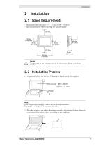
2.1 Space Requirements – Installation plate thickness: 1.5 - 7.5 mm (0.06 - 0.3 inch) – Space requirements when installing the operator panel: 100 mm (4.0 inch) 50 mm (2.0 inch) 100 mm (4.0 inch) 202 mm (7.95 inch) Caution The openings on the enclosure are for air convection. Do not cover these openings. 2.2 Installation Process 1. Unpack and check the delivery. If damage is found, notify the supplier. Note: Place the operator panel on a stable surface during installation. Dropping it or letting it fall may cause damage. 2. Place the panel cut out where the operator panel is to be situated,...
Open the catalog to page 9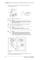
Installation 3. Secure the operator panel in position, using all the fastening holes and the provided brackets and screws: 4. Connect the cables in the specified order. A Caution Ensure that the operator panel and the controller system have the same electrical grounding (reference voltage level), otherwise errors in communication may occur. Use an M5 screw and a grounding conductor (as short as possible) with a cross-section of minimum 2.5 mm2. Caution - Use only shielded communication cables. - Separate high voltage cables from signal and supply cables. Caution - The operator panel must be...
Open the catalog to page 10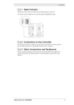
2.2.1 Mode Switches All mode switches must be in OFF position during operator panel use. The mode switches should not be touched unless by qualified personell. 2.2.2 Connections to the Controller For information about the cables to be used when connecting the operator panel to the controller, please refer to the help file for the driver in question. 2.2.3 Other Connections and Peripherals Cables, peripheral equipment and accessories must be suitable for the application and its environment. For further details or recommendations, please refer to the supplier.
Open the catalog to page 11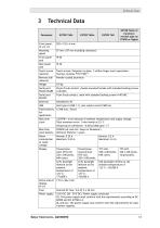
Technical Data Technical Data EXTER T60m of hardware version type no 07600 or higher Front panel, WxHxD Mounting depth Front panel seal Rear panel seal Touch screen material Touch screen: Polyester on glass, 1 million finger touch operations. Overlay: Autotex F157/F207 *. Reverse side material Powder-coated aluminum 25-pin D-sub contact, chassis-mounted female with standard locking screws 4-40 UNC. 9-pin D-sub contact, male with standard locking screws 4-40 UNC. Host type A (USB 1.1), max output current 500 mA Flash memory for application Real time clock ±20 PPM + error because of ambient...
Open the catalog to page 13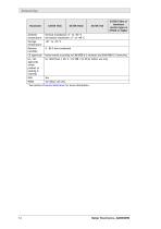
Technical Data EXTER T60m of hardware version type no 07600 or higher Ambient temperature Vertical installation: 0 ° to +50 °C Horizontal installation: 0 ° to +40 °C Storage temperature Relative humidity Noise tested according to EN61000-6-3 emission and EN61000-6-2 immunity. UL, cUL approvals (when product or packing is marked) UL 1604 Class I, Div 2 / UL 508 / UL 50 4x indoor use only * See section Chemical Resistance for more information.
Open the catalog to page 14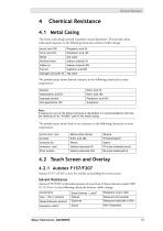
Chemical Resistance Chemical Resistance 4.1 Metal Casing The frame and casing material is powder-coated aluminum. This powder paint withstands exposure to the following chemicals without visible change: Acetic acid 10% Distilled water The powder paint shows limited resitance to the following chemicals at room temperature: Butanol Isopropyl alcohol Note: If exposure to any of the above chemicals is demanded, it is recommended to first test the chemical on an “invisble” spot of the metal casing. The powder paint shows little or no resistance to the following chemicals at room temperature:...
Open the catalog to page 15All Beijer Electronics catalogs and technical brochures
-
 TOSIBOX® Lock 150
2 Pages
-
 TOSIBOX® Lock 200
2 Pages
-
 C2 series
3 Pages
-
 X2 series
17 Pages
-
 iX T7A-SC
8 Pages
-
 iX T7A
2 Pages
-
 iX T4A-SC
8 Pages
-
 iX T4A
2 Pages
-
 X2-brochure_BREN630
19 Pages
-
 iX T10F-2
2 Pages
-
 iX T7F-2
2 Pages
-
 iX T5F-2
2 Pages
-
 iX T7AM
2 Pages
-
 PPC T7BR
3 Pages
-
 PPC T15BR
3 Pages
-
 T12C
T12C2 Pages
-
 T15C
T15C2 Pages
-
 T21C
T21C2 Pages
-
 EPC Box C2D
2 Pages
-
 iX Panel TA70
2 Pages
-
 EPC T190 C2D
2 Pages
-
 iX Panel TA150
2 Pages
-
 TxA Operator Panels
2 Pages
-
 EXTER K10
28 Pages
-
 H-T60t
8 Pages
-
 iX Panel TA100
2 Pages
-
 TxC Operator Panels
2 Pages
-
 EPC T170 C2D
2 Pages
-
 EPC T150 C2D
2 Pages
-
 iX T15BR
3 Pages
-
 H-series
8 Pages
-
 EXTER T150
26 Pages