
- Catalogs
- Beagleboard.org
- PocketBeagle

PocketBeagle
PocketBeagle
PocketBeagle is a compact, open-source USB-key-fob computer running Linux, designed for both beginners and professionals. It offers a low-cost, easy-to-use development platform with web browser-based development, leveraging various libraries and tutorials. The board boots from a microSD card loaded with a Linux distribution, supporting high-level programming languages and existing drivers.
This section outlines the document and board change history, including conversion to .rst format, hosting on GitLab, and board revisions addressing issues like GPIO labeling and component substitutions.
Instructions are provided for connecting PocketBeagle to a PC using Debian images. The package includes the PocketBeagle board and a getting started card. It is powered via a microUSB cable and can be accessed as a USB storage drive or through a web browser. Additional power may be required for add-on boards.
PocketBeagle features a System in Package (SiP) design with connectivity options including expansion headers, a microSD connector, and a USB 2.0 connector. It supports multiple boot modes and power configurations.
This section covers the design of the OSD3358-SM SiP, including power signals, JTAG, USB, and analog signals, as well as the microSD connection, USB connector, power button design, user LEDs, and JTAG pads.
PocketBeagle includes expansion header connectors, a P1 and P2 header, and a mikroBUS socket for additional connections. Instructions for setting up an additional USB connection are also provided.
This section discusses support for PocketBeagle capes, which are add-on boards that extend the functionality of the PocketBeagle.
Details on the dimensions and weight of the PocketBeagle are provided.
Information on hardware design, software updates, export information, RMA support, and getting help is included to assist users in troubleshooting and maintaining their PocketBeagle.
To begin using the PocketBeagle, insert the microSD card and access the Quick Start Guide via the URL
file:///Volumes/BEAGLEBONE/START.htm. Follow the guide to enable a network connection by copying the appropriate IP address into your browser, appending :3000 to launch Visual Studio Code for development.Navigate to
examples/BeagleBone/Black/seqLEDs.py to start coding. The provided Python script blinks the USR LEDs in sequence. Execute the script in the terminal to see the LEDs flash.There are two methods to power down the PocketBeagle: a standard power down by tapping the power button or a hard power down by holding the button for 10 seconds. To power up again, follow the specific instructions based on the power down method used.
The PocketBeagle is built around the Octavo Systems OSD335x-SM System-In-Package, featuring a Texas Instruments AM3358 processor, 512MB DDR3 RAM, and various connectivity options. It supports expansion through PocketCapes and Click Boards.
The board includes a 1GHz ARM Cortex-A8 processor, PowerVR SGX530 graphics engine, and multiple I/O options such as USB, UART, I2C, SPI, PWM, and CAN. It supports booting from microSD, USB, and serial ports.
PocketBeagle offers extensive connectivity through dual rail expansion headers, a microSD slot, and a USB 2.0 connector. The board can be powered via USB, a power supply, or expansion header pins.
The board supports three boot modes: SD Boot, USB Boot, and Serial Boot. Power can be sourced from a USB port, power supply, or expansion headers.
JTAG pads are available for optional connection to a JTAG emulator. Serial debugging is supported via UART0, providing access to boot messages and console access.
Detailed schematics for the PocketBeagle are available, covering the OSD3358-SM SiP design, microSD connection, USB connector, and power button design.
This document provides a detailed hardware design overview of the PocketBeagle, focusing on various components such as user LEDs, JTAG pads, PRU-ICSS, and connectors.
The PocketBeagle features four user-programmable LEDs. The control signals and pins for these LEDs are detailed in Table 6.1. A logic level of '1' activates the LEDs.
There are seven pads on the PocketBeagle for JTAG debugging, with additional information available on the Texas Instruments website.
The Programmable Real-Time Unit Subsystem and Industrial Communication SubSystem (PRU-ICSS) is part of the AM3358 processor. It includes dual 32-bit RISC cores, data and instruction memories, internal peripheral modules, and an interrupt controller. The PRU-ICSS allows for fast real-time responses and specialized data handling. Access to PRU pins is provided through PocketBeagle’s expansion headers.
- Two independent programmable real-time cores
- 32-Bit Load/Store RISC architecture
- 8K Byte instruction RAM per core
- 8K Bytes data RAM per core
- 12K Bytes shared RAM
- Operating frequency of 200 MHz
- Fast I/O interface with 16 input and 16 output pins per PRU core
The PocketBeagle includes two 36-pin expansion header connectors labeled P1 and P2. These connectors are compatible with standard expansion items. All signals on the expansion headers are 3.3V unless otherwise indicated. It is crucial not to connect 5V logic level signals to these pins to avoid damaging the board.
- Do not apply voltage to any I/O pin when power is not supplied to the board.
- No pins should be driven until after the NRESET line goes high.
The document provides detailed pin assignments for each header, with a color-coded chart showing the most popular functions of PocketBeagle’s Expansion Header pins.
The PocketBeagle is a compact single-board computer with dimensions of 2.21” x 1.38” (56mm x 35mm) and a maximum height of 0.197” (5mm). It features a 4-layer PCB with a thickness of 1.6mm and is RoHS compliant. The board weighs 10g.
The PocketBeagle includes expansion headers designed to accommodate up to two mikroBUS Click Boards simultaneously. The mikroBUS standard uses a pair of 1×8 female headers with a standardized pin configuration, including SPI, UART, I2C communication pins, and additional pins for PWM, Interrupt, Analog input, Reset, and Chip select. Power is supplied through +3.3V and 5V groups.
An additional USB connection can be added using a microUSB breakout, configured by default to operate as a host.
Recommendations for building PocketBeagle Cape designs are available, with discussions hosted on the PocketBeagle forum.
The PocketBeagle's mechanical specifications include a PCB size of 55mm x 35mm and a rough model available for reference.
Support for PocketBeagle is provided through the BeagleBoard.org community. Hardware design documentation, including schematics and layouts in PDF, EAGLE, and KiCAD formats, is available online. Software updates can be downloaded from the BeagleBoard website. For defective boards, RMA support is available through the manufacturer's website.
Catalog excerpts
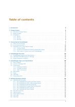
5 PocketBeagle High Level Specification 25 6 Detailed Hardware Design 31
Open the catalog to page 2
8 PocketBeagle Cape Support 53
Open the catalog to page 3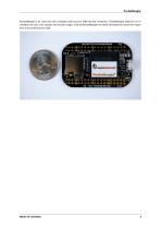
PocketBeagle is an ultra-tiny-yet-complete open-source USB-key-fob computer. PocketBeagle features an incredible low cost, slick design and simple usage, making PocketBeagle the ideal development board for beginners and professionals alike.
Open the catalog to page 4
Introduction This document is the System Reference Manual for PocketBeagle and covers its use and design. PocketBeagle is an ultra-tiny-yet-complete Linux-enabled, community-supported, open-source USB-key-fob-computer. PocketBeagle features an incredible low cost, slick design and simple usage, making it the ideal development board for beginners and professionals alike. Simply develop directly in a web browser providing you with a playground for programming and electronics. Exploring is made easy with several available libraries and tutorials with many more coming. PocketBeagle will boot directly...
Open the catalog to page 6
This section describes the change history of this document and board. Document changes are not always a result of a board change. A board change will always result in a document change.2.1 Document Change HistoryTable 2.1: Change HistoryRev Changes Date By A.x Production Document December 7,2017 JK 0.0.5 Converted to .rst and gitlab hosting July 21, 2022 DK Table 2.2: Board HistoryRev A1 Changes Date Preliminary Production. Fixed mikroBUS Click reset pins (made GPIO). Fixed label on P2_24. Was labeled GPIO48, should be GPIO44. Because there are 2 TI parts which have long lead-time, we made the...
Open the catalog to page 8
PocketBeagle a BeagleBoard.org Foundation project. The board never worked because the 32kHz and 24MHz crystals were backwards and Michael Welling decided to pick it up and redo the design in KiCad as a four-layer board. Jason paid for some prototypes and this resulted in the first successful "PocketBone”, a fully-open-source 1-GHz Linux computer in a fitting into a mini-mint tin. The Rev A1 of PocketBeagle was a prototype not released to production. A few lines were wrong to be able to control mikroBUS Click add-on board reset lines and they were adjusted. The Rev A2 of PocketBeagle was released...
Open the catalog to page 9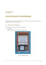
Connecting Up PocketBeagle This section provides instructions on how to hook up your board. The most common scenario is tethering PocketBeagle to your PC for local development. 3.1 What’s In the Package In the package you will find two items as shown in figures below. • PocketBeagle • Getting Started instruction card with link to the support URL.
Open the catalog to page 10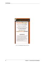
Fig. 3.2: PocketBeagle Package Insert front Chapter 3. Connecting Up PocketBeagle
Open the catalog to page 11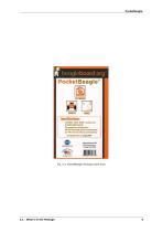
Fig. 3.3: PocketBeagle Package Insert back
Open the catalog to page 12
3.2 Connecting the board This section will describe how to connect to the board. Information can also be found on the Quick Start Guide that came in the box. Detailed information is also available at beagleboard.org/getting-started The board can be configured in several different ways, but we will discuss the most common scenario. Future revisions of this document may include additional configurations. 3.3 Tethered to a PC using Debian Images In this configuration, you will need the following additional items: • microUSB to USB Type A Cable • microSD card (>=4GB and <128GB) The board is powered...
Open the catalog to page 13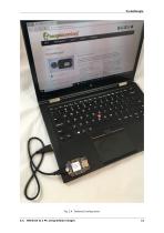
3.3. Tethered to a PC using Debian Images
Open the catalog to page 14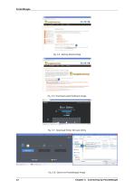
f'f beogleboard.org BeagleBoard.org Latest Firmware Images Stretch (or BeagieBoard-Xl5 via microSD card Fig. 3.7: Download Etcher SD Card Utility Search Downloads File folder File folder Select image 1. Keysi ghtHan dhel dMeterLogger.i. 1.5113... 10/12/2017 1048 jk MobaXtermJn sta ller.vl 0.4 10/30/2017 1 0:38 Compressed (zipp, Compressed (app. Fig. 3.8: Select the PocketBeagle Image 12 Chapter 3. Connecting Up PocketBeagle
Open the catalog to page 15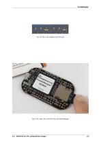
Fig. 3.9: Burn the Image to the SD Card Fig. 3.10: Insert the microSD Card into PocketBeagle 3.3. Tethered to a PC using Debian Images
Open the catalog to page 16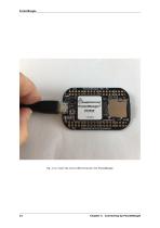
■ i. bea.glcboB.rd .org PcckfetBtogle' OCTAVO 1 737^1 Fig. 3.11: Insert the micro USB Connector into PocketBeagle 14 Chapter 3. Connecting Up PocketBeagle
Open the catalog to page 17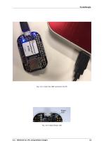
Fig. 3.12: Insert the USB connector into PC 3.3. Tethered to a PC using Debian Images
Open the catalog to page 18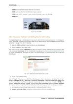
• USER0 is the heartbeat indicator from the Linux kernel. • USER1 turns on when the microSD card is being accessed • USER2 is an activity indicator. It turns on when the kernel is not in the idle loop. • USER3 idle Accessing the Board and Getting Started with Coding The board will appear as a USB Storage drive on your PC after the kernel has booted, which will take approximately 10 seconds. The kernel on the board needs to boot before the port gets enumerated. Once the board appears as a storage drive, do the following: 1. Open the USB Drive folder to view the files on your PocketBeagle. 2. Launch...
Open the catalog to page 19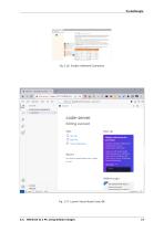
Fig. 3.16: Enable a Network Connection Fig. 3.17: Launch Visual Studio Code IDE 3.3. Tethered to a PC using Debian Images
Open the catalog to page 20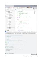
The code should match the code below, if you can't find it, copy and paste the below code into the editor # // Blinks the USR LEDs in sequence. import time import os # Turn off triggers for i in range(LEDs): # print(LEDPATH+str(i)+”/trigger”) f = open(LEDPATH+str(i)+”/trigger”, ”w”) f.write(”none”) f. close() # Open a file for each LED (continues on next page) 18 Chapter 3. Connecting Up PocketBeagle
Open the catalog to page 21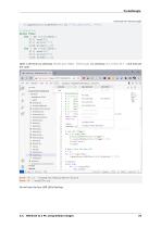
(continued from previous page) f.append(open(LEDPATH + str(i)+ ”/brightness” , ”w”)) # Sequence while True: for i in range(LEDs): f[i].seek(0) f[i].write(”1”) time.sleep(0.25) for i in range(LEDs): f[i].seek( 0) f[i].write(”0”) time.sleep(0.25) Open a terminal by selecting Terminal/New Terminal (or pressing Ctrl + Shift + ' ) and execute the code: bone:~$ cd ~/examples/BeagleBone/Black bone:~$ ./seqLEDs.py You will see the four USR LEDs flashing. 3.3. Tethered to a PC using Debian Images 19
Open the catalog to page 22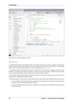
Type CTRL+C to stop the program running. Powering Down 1. Standard Power Down Press the power button momentarily with a tap. The system will power down automatically. This will shut down your software with grace. Software routines will run to completion. | The Standard Power Down can also be invoked from the Linux command shell via sudo halt. 2. Hard Power Down Press the power button for 10 seconds. This will force an immediate shut down of the software. For example you may lose any items you have written to the memory. Holding the button longer than 10 seconds will perform a power reset and...
Open the catalog to page 23All Beagleboard.org catalogs and technical brochures
 BeagleY-AI
133 Pages
 BeagleV-Fire
99 Pages
 BeagleBone Blue
27 Pages
 BeagleBone Black
109 Pages
 BeagleV-Ahead
57 Pages
 BeagleBone AI-64
132 Pages
 BeagleConnect Freedom
37 Pages