
- Catalogs
- BDC ELECTRONIC S.r.l.
- SPEED SENSORS

SPEED SENSORS

SPEED SENSORS
- Working Voltage: 10 ÷ 30 Vdc
- Max Ripple: 10%
- No-load Supply Current: <15 mA
- Rated Operational Current: 200 mA
- Voltage Drop: < 1.5 V
- Switching Hysteresis: <10% Sn
- Repeat Accuracy: < 2% Sn
- Max Detectable Interval: 2 min
- Detectable Start-up Time: 0 ÷1 min (default 2 sec.)
- Temperature Range: -20 ÷ +70°C
- Max Thermal Drift: ±10%
- Degree of Protection: IP67
- Status Indicator: Yellow LED
- EMC Compliance: EN60947-5-2
- Shock and Vibration Resistance: EN60068-2-27, EN60068-2-6
- Procedure 1: Connect the Teach input to the power supply before turning on the machine. The sensor calculates the threshold as 80% of the maximum speed.
- Procedure 2: Set the desired speed as the threshold by temporarily connecting the Teach input to the power supply.
Catalog excerpts
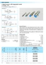
SPEED SENSORS • Speed sensors with integrated control • 3 wires - d.c. • Connector output M12 x 1 Housing I-11 L5 L1 General Features: Flush mounting Non flush mounting • Housing 8 mm: • Housing 12 - 18 - 30 mm: • Sensing face: Technical data: • • • • • • • • • • • • • • • • Working voltage: 10 ÷ 30 Vdc Max ripple: 10% No-load supply current: <15 mA 200 mA Rated operational current (Ie): Voltage drop: < 1,5 V Switching hysteresis (H): <10% Sn Repeat accuracy (R ): < 2% Sn Maximum detectable interval (between two pulses): 2 min Detectable start-up time (T1): 0 ÷1 min (default 2 sec.) Temperature range: - 20 ÷ + 70°C ±10% Max thermal drift of sensing distance Sn: Degree of protection: IP67 Status indicator: yellow LED = out ON; frequency over the threshold Protected against short-circuit and overload Electromagnetic compatibility (EMC) according to EN60947-5-2 Shock and vibration resistance according to EN60068-2-27 e EN60068-2-6 ORDERING REFERENCES PNP (positive switching) 1 brown 2 white 4 black 3 blue stainless steel nickel plated brass plastic Female connector (see page H -1) Nominal sensing distance ( Sn )±10% These sensors allow to control with extremely high precision the rotation of a toothed wheel or reference marks, switching off the load or giving an alarm in case the speed goes down the minimum threshold. Thanks to the extremely wide measuring range they can be even used to control repetitive operations, signalling in case of unavoided stops. Further delays or other special functions are implementable upon specific request. The output is protected against connection mistakes, overvoltages on lines, and short circuit of the load. The connection is possible with a 4 wires M12x1 connector which must be ordered separately. BDC Electronic - Viale Lidice, 37/39 - 10095 Grugliasco (To) - Italy -Tel. (+39)011.31.49.021/022 Fax (+39) 011.
Open the catalog to page 1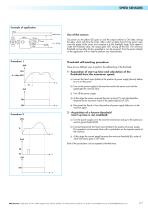
SPEED SENSORS Example of application Motor Motor Power Sensor 2 White 4 Black 3 Blue On power on, the yellow LED goes on and the output switches in ON state, driving the relay, which will drive the motor. After a start up delay time (T1) the sensor measures the speed of the motor and compare it to the threshold value. If the speed is under the threshold value, the output goes OFF, turning off the LED. The minimum threshold can be either factory presetted or can be acquired from the sensor directly on the application with no need to perform any measurement. Threshold self-teaching procedure: There...
Open the catalog to page 2All BDC ELECTRONIC S.r.l. catalogs and technical brochures
 NAMUR SERIES
1 Page
 Connector output M8x1
1 Page
 CONNECTORS CABLED ON SENSORS
33 Pages
 CAPACITIVE SENSORS
12 Pages
 INDUCTIVE SENSORS
92 Pages
 ATEX SENSORS CATALOGUE
97 Pages
 DF.../...A series
1 Page
 DCX.../...A series
1 Page
 DCZ.../...A series
1 Page
 General Catalogue
213 Pages


Archived catalogs

- Data connector
- Metal connector
- Proximity switch
- Screw-in connector
- Industrial connector
- IP67 connector
- Cylindrical proximity sensor
- Male connector
- Inductive proximity sensor
- Current connector
- Signal amplifying integrated circuit
- Cable connector
- IP67 proximity sensor
- Straight connector
- Tilt sensor
- RF connector
- DIN connector
- DC proximity sensor