- Catalogs
- BBH Products GmbH
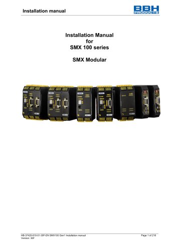
- Installation Manual for SMX 100 series SMX Modular
Installation Manual for SMX 100 series SMX Modular
1 /218Pages
Installation Manual for SMX 100 series SMX Modular
1 /218Pages
Catalog excerpts

Installation manual Installation Manual for SMX 100 series SMX Modular
Open the catalog to page 1
Installation manual Installation manual for base devices of SMX100 series - SMX100-1 (/4x, /5x) - SMX100-2 (/4x, /5x) - SMX100-4 (/4x, /5x) and the expansion modules - SMX121 - SMX121-2 Options: /5x - Standard field bus /4x - Standard field bus and safety protocol A - Safe, analog inputs
Open the catalog to page 2
Installation manual Note: The German version if the original version of the installation manual Status: 07/2022 Valid from FW release 2.0.2.46 Subject to change without prior notification The contents of this documentation has been collated with greatest care and corresponds with our present status of information. However, we would like to point out, that this document cannot always be updated at the same time as the technical further development of the products. Information and specifications can be changed at any time. Please keep yourself informed about the current version under www.bbh-products.de....
Open the catalog to page 3
Installation manual 1 Important notes Definition of individual target groups Project engineers for safe drive systems: Engineers and technicians Assembly, electric installation, maintenance and replacement of devices: Maintenance electricians and service technicians Commissioning, operation and configuration: Technicians and engineers 1.1 Definitions The designation SMX100 is used as generic term for all derivatives from the SMX100 product range. Wherever this description refers to a certain derivative, the complete designation is used. The term "safe" used in the following text in any case refers...
Open the catalog to page 7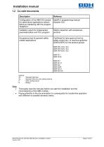
Installation manual1.2 Co-valid documents Description Options: /5x - Standard field bus /4x - Standard field bus and safety protocol A - Safe, analog inputs Note: • Thoroughly read the manuals before you start the installation and the commissioning of the SMX module. • Paying attention to the documentation is a prerequisite for trouble-free operation and fulfilment of possible warranty claims.
Open the catalog to page 8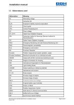
Installation manual1.3 Abbreviations used Abbreviation
Open the catalog to page 9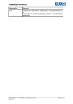
Installation manual Abbreviation
Open the catalog to page 10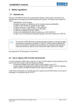
Installation manual 2 Safety regulations 2.1 Intended use Devices of the SMX100 series are programmable fail-safe control system intended for the establishment of emergency shut-down features and functions. The devices are intended for use in - EMERGENCY STOP facilities, - as safety component as defined by the EC machine directive 2006/42/EG, - as PES for risk reduction as defined by IEC 61508, - in safety circuits acc. to IEC 60204-1 u. IEC 60204-32, - as PES for functional safety as defined by IEC 62061, - as SRP/CS as defined by EN ISO 13849-1, - as device for establishing the safety functions...
Open the catalog to page 11
Installation manual 2.3 General safety regulations Safety note: • In order to avoid damage to persons and property only qualified personnel is entitled to work on the device. The term qualified personnel refers to persons who have successfully completed electrotechnical training and are fully familiar with the applicable rules and standards of electrical engineering. The qualified person must become familiar with the operating instructions (see IEC 364, DIN VDE 0100). The qualified person must have profound knowledge of the national accident prevention regulations The use of the device must be...
Open the catalog to page 12
Installation manual WARNING: Using our devices contrary to the rules and conditions specified hereunder can lead to injuries or fatalities as well as damage to connected devices and machines! This will also cause the loss of all warranty and compensation claims against BBH. 2.4 Operation and service The module must always be de-energized before installation and removal, or before disconnecting signal lines. For this purpose, all live supply lines to the device must be checked for safe isolation from supply. When installing or removing the module appropriate measures must be applied to prevent...
Open the catalog to page 13
Installation manual 3 Device types The series SMX100 consists of - base devices SMX100-1, SMX100-2, SMX100-4 optionally with o integrated communication modules ▪ Standard field bus SMX100-x(/5x) or ▪ Safe field bus SMX100-x(/4x) - central I/O expansion modules SMX131, SMX131R - central axis expansion modules SMX121, SMX121-2, SMX122 or SMX122A, and SMX122-2 or SMX122-2A Basic devices SMX100-x series is a modular safety controller. The device is open programmable for safe processing of EMERGENCY OFF buttons, two-handed controls, light barriers, operating mode selection switches etc. as well as...
Open the catalog to page 14
Installation manual • Safety note: The 24V DC supply terminals of the SMX module must be fused with an external back-up fuse of 2A (24VDC). Recommended fuse type: 2A circuit breaker (Class B) or fuse (fast-blow). Depending on the current requirement, fusing can be done in total or per I/O group.
Open the catalog to page 15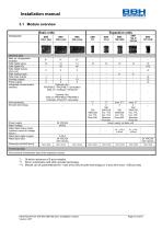
Installation manual3.1 Module overview
Open the catalog to page 16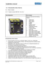
Installation manual 3.2 Characteristic data of device 3.2.1 Basic modules 3.2.1.1 System module SMX100-1 (/4x, /5x) Type designation Device design Design of module with the following periphery: configuration interface 1 function button 14 status LEDs for inputs 2 status LEDs for pulse outputs 2 status LEDs for relay outputs 2 status LEDs for outputs HISIDE Characteristics of the module: • Logic processing up to Pl e acc. to EN ISO 13849-1 or SIL 3 acc. to EN 61508 • 14 safe inputs, 3 cut-off channels, of which 1 safe relay output and 2 auxiliary outputs integrated in the base device • Expandable...
Open the catalog to page 17
standard fieldbus communication (/4x) via CAN bus 2.0 interface, CANopen, PROFIBUS, PROFINET, EtherCAT, DeviceNet, or safe fieldbus communication (/5x) via PROFIsafe V 2.0 or FSoE with a higher level controller See: Chapter 3.2.3 “Optional Communication interface” Assembly on top hat rail
Open the catalog to page 18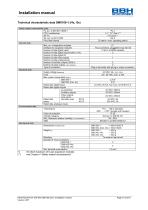
Installation manualTechnical characteristic data SMX100-1 (/4x, /5x) Safety related characteristic data (*) Of which maximum of 6 axis expansion modules (**) see Chapter 4 "Safety related characteristics"
Open the catalog to page 19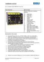
Type designation Device design Design of module with the following periphery: 14 Digital inputs configuration interface 1 Function button 14 Status LEDs for inputs 2 Status LEDs for pulse outputs 2 Status LEDs for relay outputs 2 Status LEDs for outputs HISIDE 20 Status LEDs for I/O‘s 1 Optional: Communication interface Characteristics of the module: • Logic processing up to PL e acc. to EN ISO 13849-1 or SIL 3 acc. to IEC 61508 • 20 safe I/O - configurable as input or output, 14 safe inputs, 3 cut-off channels, of which 1 safe relay output and 6 auxiliary outputs integrated in the base device...
Open the catalog to page 20All BBH Products GmbH catalogs and technical brochures
 SCU-2-EC/x
8 Pages
 SCU-1-EC/x
7 Pages
 SCU-0-EC/x
6 Pages
- Digital I/O
- IO module
- Analog I/O
- Digital IO module
- Monitoring software solution
- Interface software
- Programmable logic controller
- Programming software
- Fieldbus I/O module
- Analog IO module
- Remote I/O
- Machine software
- Remote IO module
- Ethernet programmable logic controller
- Safety software
- Networked PLC
- Fieldbus PLC
- Safety I/O
- Compact programmable logic controller
- Distributed I/O