

Series 2500

Series 2500
The MOVISTROB® products undergo extensive quality and function tests to ensure safety and performance. Users are advised to read the operating instructions thoroughly to prevent damage or injury.
General Description
The MOVISTROB® 2500 is a digital stroboscope designed for studying rapid, periodic motions through short light flashes. It is known for its high time stability, accuracy, ease of use, and low maintenance costs. The device is menu-driven, facilitating easy operation even after long periods of non-use.
Controls and Indicators
The device includes an LC-Display, arrow keys, a mode key, and a unit key. It has connections for power, external control, and a serial interface. The flash bulb is protected by a transparent cover, which can be replaced with a red filter to reduce eye strain.
Menu Structure and Mode Selection
All operating modes are accessible via a menu, allowing for frequency measurement, flashing frequency generation, and phase displacement adjustments. The menu enables easy mode switching and setting adjustments.
Individual Modes
- Frequency Measurement (MEASURE Mode): Provides precise speed measurement with high accuracy, with triggering set to line frequency or external signals.
- Phase Displacement (PHASE Mode): Synchronizes flashing with line frequency or external signals, allowing phase displacement settings.
- Flash Frequency Generation (GENERATE Mode): Generates flashing frequencies with adjustable units and a double flash function for speed adjustment.
RS 232 Serial Interface
The stroboscope can be controlled via a serial interface, allowing integration into automated systems. Data is transmitted in ASCII code, and transmission parameters can be configured in SERIAL mode.
Storing Settings
All current settings can be stored as standard settings for when the device is switched on.
The device operates with a +12V DC input across a 150 KΩ resistor for switching contact. It has four inputs ranging from 0.5 to 50V with a resistance of 50 KΩ, and a signal ground. External connections are made via a seven-pole diode plug with a bayonet lock. The socket pin assignment includes +12V DC, signal ground, and opto outputs.
2. Stroboscopic Principle
Stroboscopy allows observation of high-speed periodic motion by illuminating the object with brief light impulses. The object appears motionless or in slow-motion at the appropriate flash frequency. The highest flash frequency that produces a stopped image equals the object's revolutions. RPM and frequencies can be measured by determining the highest flash frequency or two neighboring flash frequencies.
3. Slow-Motion Cycle
If the flash frequency period deviates slightly from a whole-number multiple of the rotation time, the object appears to rotate slowly. The apparent angular speed is influenced by the deviation from the whole-number multiple.
4. Stopped Images of Phantom Objects
Stopped images can occur at other flash frequencies, representing phantom objects. These images are less distinct as the number of marks increases.
5. Objects with Finite Rotational Symmetry
For objects with symmetrical axes, stopped images result from specific flash frequency periods. Phantom images also occur under certain conditions.
6. Replacing Flash Tube
If the flash tube fails, it must be replaced by removing the protective cover and ensuring the device is off. The new tube should be inserted carefully, and the device should not be operated until the housing is closed.
7. Maintenance and Repair
If the instrument is unsafe, it should be taken out of operation. Repairs should be conducted by trained personnel or returned to the manufacturer.
8. Technical Data
The device features internal and external flash triggering, a frequency generator with a resolution of 0.01 Hz, and a frequency range of 1 Hz to 300 Hz. It supports various measurement units and has a serial interface for data exchange. The power supply ranges from 90V AC to 240V AC or DC voltage from 100V to 340V. The device dimensions are 110 mm x 206 mm x 63 mm, and it weighs approximately 0.9 kg.
Catalog excerpts
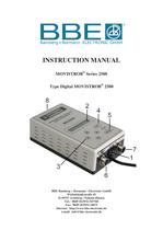
2100 + 2150 - Art.Nr. 1070, 1072, 1073, 1077_V2 table.main {} tr.row {} td.cell {} div.block {} div.paragraph {} .font0 { font:87.00pt "Georgia", serif; } .font1 { font:9.00pt "Times New Roman", serif; } .font2 { font:15.00pt "Times New Roman", serif; } .font3 { font:23.00pt "Times New Roman", serif; } .font4 { font:14.00pt "Verdana", sans-serif; } BBE Bamberg + Bormann ELECTRONIC GmbH INSTRUCTION MANUAL MOVISTROB® Sries 2500 Type Digital MOVISTROB® 2500 8 BBE Bamberg + Bormann - Electronic GmbH Wiebelsheidestrafie 45 D-59757 Arnsberg / Neheim-Husten Tel.: 0049 (0)2932-547760 Fax: 0049 (0)2932-34675 Internet: http://www.bbe-electronic.de e-mail: [email protected]
Open the catalog to page 1
2100 + 2150 - Art.Nr. 1070, 1072, 1073, 1077_V2 table.main {} tr.row {} td.cell {} div.block {} div.paragraph {} .font0 { font:9.00pt "Times New Roman", serif; } 1. Introduction Each MOVISTROB® product has to pass through various controls during its production phases and must also undergo very strict and conscientious function and quality tests before leaving the factory for delivery to our clients. We can assure you that the MOVISTROB® product you received is in strict conformity with our high quality standards and it fully meets all safety and performance requirements. All relevant data on...
Open the catalog to page 2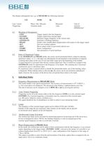
2100 + 2150 - Art.Nr. 1070, 1072, 1073, 1077_V2 table.main {} tr.row {} td.cell {} div.block {} div.paragraph {} .font0 { font:9.00pt "Times New Roman", serif; } The display subsequently has, e.g. in MEASURE the following structure: LM 49.983 Hz Line / extern Phase / Set / Measure Measured Unit of Triggerung Generate mode value measure RPM/Hz/ms/° 4.1 Meaning of Designators - LINE Trigger signal is the line frequency - EXTERN Trigger signal from external input - MEASURE Measures trigger frequency in the various units - GENERATE Generates a flashing frequency - PHASE Flashes with variable phase...
Open the catalog to page 4
2100 + 2150 - Art.Nr. 1070, 1072, 1073, 1077_V2 table.main {} tr.row {} td.cell {} div.block {} div.paragraph {} .font0 { font:9.00pt "Times New Roman", serif; } 5.2.1 Phase Input in ms By pressing the unit key (UNIT) it is also possible to set the phase displacement as a time delay between the trigger flank and flash. The previously displayed phase angle is subsequently converted into a time. The delay time can be set from 0.000 ms to 1000.00 ms. After changing to the unit " 0 " previously set phase angle is redisplayed. 5.2.2 Absolute Zero Setting The absolute zero of the phase adjuster can...
Open the catalog to page 5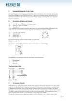
2100 + 2150 - Art.Nr. 1070, 1072, 1073, 1077_V2 table.main {} tr.row {} td.cell {} div.block {} div.paragraph {} .font0 { font:6.00pt "Arial", sans-serif; } .font1 { font:7.00pt "Arial", sans-serif; } .font2 { font:7.00pt "Times New Roman", serif; } .font3 { font:9.00pt "Times New Roman", serif; } 7. Storing all Settings in STORE Mode All current settings such as triggering or numerical values of the device can be stored by selecting the menue item STORE ( by pressing the mode key ). These are the standard settings when the device is switched on. In addition, the mode which was active before...
Open the catalog to page 7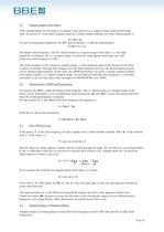
2100 + 2150 - Art.Nr. 1070, 1072, 1073, 1077_V2 table.main {} tr.row {} td.cell {} div.block {} div.paragraph {} .font0 { font:9.00pt "Times New Roman", serif; } 9.1 Stopped Image of the Object If the rotating object (or the mark) is to appear to the observer as a stopped image under stroboscopic light, the period T of the flash frequency must be a whole-number multiple n of the rotation period r: T = Tn = nr For the corresponding frequencies f = 1/T and revolutions v = 1/r the relationship is: f = fn = 1 v ■*■ n The highest flash frequency (n = 1) which produces a stopped image of the object,...
Open the catalog to page 8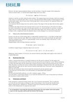
2100 + 2150 - Art.Nr. 1070, 1072, 1073, 1077_V2 table.main {} tr.row {} td.cell {} div.block {} div.paragraph {} .font0 { font:9.00pt "Times New Roman", serif; } However, the latter represent phantom objects, not the real object. Using the example of the rotating dise with an eccentric mark , it is obvious that stopped images also occur when: T=(n■*■ k ) r and / or f = ( k ■*■ n ) v, whereby n and k are whole relatively-prime numbers. The stopped image shows k marks, which are arranged in the corner of a regular k-angle. Only a very few of the theoretically infinite number of flash frequencies...
Open the catalog to page 9
2100 + 2150 - Art.Nr. 1070, 1072, 1073, 1077_V2 table.main {} tr.row {} td.cell {} div.block {} div.paragraph {} .font0 { font:8.00pt "Times New Roman", serif; } .font1 { font:9.00pt "Times New Roman", serif; } Flash Triggering: Frequency Generator: Frequency Measurement: Phase Shifter: Operator Guidance; Serial Interface: Puls Output: Display: Flash bulb: Flash Duration: Light Intensity: Automatic Flash Frequency Adjustment: Power Supply: - internal with quarz stable generator - synchronous with line frequency - external via signal: positiv flank triggered; floating input 0.9 Hz-< f < 1.66 Khz;...
Open the catalog to page 10All BBE Bamberg + Bormann-Electronic GmbH catalogs and technical brochures
 MINISTROB 2000N/S-EXT
1 Page
 Type 600 KS
1 Page
 Type 915
1 Page
 MINISTROB MS 2006
1 Page
 MOVISTROB® 400.00-S/LW2
1 Page
 MOVISTROB 600.00-2GS-19
1 Page
 MOVISTROB 600.00
1 Page
 MOVISTROB® 500.00
1 Page
 MOVISTROB® 420.00-S/2HL
1 Page
 MOVISTROB® 420.00
1 Page
 MOVISTROB® 400.01
1 Page
 MOVISTROB® 400.00
1 Page
 MOVISTROB® Typ 350.10-99
1 Page
 MOVISTROB® Typ 350.00-99
1 Page
 MOVISTROB® Typ 300.00-99
1 Page
 MOVISTROB® 350.00-BD
1 Page
 Series 3000
8 Pages
 Series 2800
6 Pages
 Series 2100
7 Pages
 Series 2006
6 Pages
 Series 1000
27 Pages
 Series 600
10 Pages
 Series 500
8 Pages
 Series 400
7 Pages
 300 series
7 Pages
 compact stroboscope
7 Pages
 portable stroboscope
7 Pages


