
- Catalogs
- BBE Bamberg + Bormann-Electronic GmbH
- Compact microprocessor-controlled stroboscope with interface.

Compact microprocessor-controlled stroboscope with interface.

Compact microprocessor-controlled stroboscope with interface.
The MOVISTROB® product is subjected to comprehensive quality and functionality tests to ensure adherence to high safety and performance standards. Users are encouraged to read the operating instructions thoroughly to avoid damage or injury.
A stroboscope is a device used to study rapid, periodic motions by producing short light flashes, making fast-moving objects appear stationary. It is beneficial for speed measurement without mechanical interference. Digital stroboscopes offer high accuracy, ease of use, and low maintenance.
The device includes an LC-Display, arrow keys, a mode key, and a unit key. It has connections for power cords, external control, and a serial interface, along with a flash bulb and reflector cover. A red filter cover reduces eye strain but decreases light intensity.
All operating modes are accessible via a menu, allowing users to select modes such as MEASURE, GENERATE, and PHASE, and adjust settings using the mode and arrow keys.
- MEASURE Mode: Enables precise speed measurement with options to change units between RPM, Hz, or ms. External triggering requires a disturbance-free signal.
- PHASE Mode: Synchronizes flashes with a trigger signal, allowing phase displacement settings. Limits are set to prevent device overload.
- GENERATE Mode: Produces flashing frequencies with high accuracy. The double flash function helps adjust to the speed of the observed object.
The stroboscope can be controlled via a computer, facilitating integration into automated systems. Data is transmitted in ASCII code, with configurable transmission parameters in SERIAL mode.
Current settings can be saved as standard settings for future use, ensuring the device retains configurations upon restart.
The device includes various inputs and outputs for external triggering and synchronous output, with specific voltage and signal ground requirements.
Stroboscopy uses high-speed light flashes to study rapid motions, making them appear stationary for analysis.
The document explains methods to observe periodic motion too fast for the naked eye by using periodic light flashes, making the object appear motionless or in slow motion. Flickering is unavoidable at flash rates below 30 Hz.
To achieve a stopped image under stroboscopic light, the flash frequency must be a whole-number multiple of the object's rotation period. Phase stability can be achieved by controlling the flash frequency externally.
RPM can be measured by determining the highest flash frequency that results in a stopped image or by calculating the rotational frequency from two neighboring flash frequencies.
If the flash frequency slightly deviates from a whole-number multiple of the rotation time, the object appears to rotate slowly. The apparent angular speed can be calculated and compared to the true angular speed.
Phantom objects can appear at certain flash frequencies, showing multiple marks arranged in a regular pattern. These images are less distinct as the number of marks increases.
Objects with symmetrical axes can produce stopped images of both real and phantom objects. The document provides formulas for calculating these images.
Instructions are provided for replacing the flash tube, including safety precautions and steps to ensure proper installation.
The document advises taking the instrument out of operation if it is unsafe and recommends repairs be conducted by trained personnel.
Detailed technical specifications are provided, including flash triggering methods, frequency generator resolution, frequency measurement accuracy, phase shifter details, operator guidance, serial interface specifications, pulse output, display characteristics, flash bulb type, power supply requirements, and physical dimensions.
Catalog excerpts
BBE Bamberg + Bormann - Electronic GmbHWiebelsheideststrae 45D - 59757 Arnsberg / Neheim - HstenTel.: 0049 (0)2932 - 547760Fax 0049 (0)2932 - 34675I >
Open the catalog to page 1
Each MOVISTROB > product has to pass through various controls during its production phases and must alsoundergo very strict and conscientious function and quality tests before leaving the factory for delivery to our clients.We can assure you that the MOVISTROB > ή product you received is in strict conformity with our high qualitystandards and it fully meets all safety and performance requirements. All relevant data on this instrument are electronically stored and can be recalled at any time.Upon delivery, the instrument complies with the required safety regulations. To maintain this condition...
Open the catalog to page 2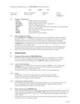
MEASURE the following structure: LM49.983Hz Line / externPhase / Set / MeasureMeasuredUnit ofTriggerungGenerate modevaluemeasureRPM/Hz/ms/ > - LINE Trigger signal is the line frequency - EXTERN Trigger signal from external input - MEASURE Measures trigger frequency in the various units - GENERATE Generates a flashing frequency - PHASE Flashes with variable phase displacement with respect to the trigger signal - SET Sets zero of phase adjuster - MOV Moves phase relativ to previously altered zero - STORE Stores configuration - SERIAL Sets parameters of serial interfaces > In the GENERATE and PHASE...
Open the catalog to page 4
By pressing the unit key ( UNIT ) it is also possible to set the phase displacement as a time delaybetween the trigger flank and flash. The previously displayed phase angle is subsequently convertedinto a time. The delay time can be set from 0.000 ms to 1000.00 ms. After changing to the unit " > "previously set phase angle is redisplayed. > The absolute zero of the phase adjuster can be adjusted by replacing " MOV " with " SET " in theMenue. The display subsequently has the following structure, for example in the PHASE mode: SL212.00 The absolute zero can now be set. All angles entered under...
Open the catalog to page 5
All current settings such as triggering or numerical values of the device can be stored by selecting themenue item STORE ( by pressing the mode key ). These are the standard settings when the device isswitched on. In addition, the mode which was active before storage is automatically active when thedevice is switched on. > -.3 +12V DC across 150 K Ω for switching contact - 4 Input ( 0.5 - 50V, R = 50 K Ω ) - 5 Signal ground- The connection of an external transmitter takes place via a seven pole diode plug with bayonet lock.-.The socket pin assignment for external triggering and synchronous output...
Open the catalog to page 7
If the rotating object (or the mark) is to appear to the observer as a stopped image under stroboscopiclight, the period T of the flash frequency must be a whole-number multiple n of the rotation period r : T = Tn = nr For the corresponding frequencies f = 1/T and revolutions v = 1/r the relationship is: f = fn = 1 v 緷 n The highest flash frequency (n = 1) which produces a stopped image of the object, i.e. the markequals the revolutions: f1 = v (stopped images in which the mark appears more than once stillresult from flash frequency f > f1 ).The observed phase of the rotation in stopped image,...
Open the catalog to page 8
Stopped images of rotating objects results from flash frequency periods Tn = nr , and also at other flashfrequencies. However, the latter represent phantom objects, not the real object. Using the example of the rotating discwith an eccentric mark , it is obvious that stopped images also occur when: T = ( n 緷 k ) r and / or f = ( k 緷 n ) v, whereby n and k are whole relatively-prime numbers. The stopped image shows k marks, which are arrangedin the corner of a regular k -angle. Only a very few of the theoretically infinite number of flash frequencies resultin observable images, since at each corner...
Open the catalog to page 9
internal with quarz stable generator - synchronous with line frequency- external via signal: positiv flank triggered; floating input 0.9 Hz > Resolution:0.01 Hz Frequency range:1 Hz < f < 300 HzUnits of measurement:Hz, Rpm, ms Double flashing function for about 1.1 s > Accuracy:f = 10 > 5 Frequency range0.9 < f < 1.66 Khz Units of measurement:Hz, RPM, ms > In : resolution: 0.1а ; range 0 - 359.9а In ms: max.. resolution: 1s; range: 0 ms < t < 1000 ms Frequency range: 0.9 Hz < f < 302 Hz Flash deactivation at excessive frequency;phase shifter zero is variable > menue - orientated All settings...
Open the catalog to page 10All BBE Bamberg + Bormann-Electronic GmbH catalogs and technical brochures
 MINISTROB 2000N/S-EXT
1 Page
 Type 600 KS
1 Page
 Type 915
1 Page
 MINISTROB MS 2006
1 Page
 MOVISTROB® 400.00-S/LW2
1 Page
 MOVISTROB 600.00-2GS-19
1 Page
 MOVISTROB 600.00
1 Page
 MOVISTROB® 500.00
1 Page
 MOVISTROB® 420.00-S/2HL
1 Page
 MOVISTROB® 420.00
1 Page
 MOVISTROB® 400.01
1 Page
 MOVISTROB® 400.00
1 Page
 MOVISTROB® Typ 350.10-99
1 Page
 MOVISTROB® Typ 350.00-99
1 Page
 MOVISTROB® Typ 300.00-99
1 Page
 MOVISTROB® 350.00-BD
1 Page
 Series 3000
8 Pages
 Series 2800
6 Pages
 Series 2500
10 Pages
 Series 2100
7 Pages
 Series 2006
6 Pages
 Series 1000
27 Pages
 Series 600
10 Pages
 Series 500
8 Pages
 Series 400
7 Pages
 300 series
7 Pages
 compact stroboscope
7 Pages
 portable stroboscope
7 Pages


