- Catalogs
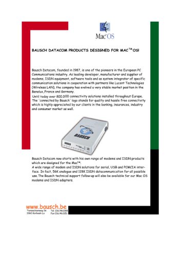
- Bausch Datacom
- MA-DF560
- Company
- Products
- Catalogs
- News & Trends
- Exhibitions
MA-DF560
1 /77Pages

MA-DF560
1 /77Pages
Catalog excerpts
Allied Data TECHNOLOGIES
Open the catalog to page 1
DISCLAIMER This manual by ALLIED DATA TECHNOLOGIES B.V. (hereinafter referred to as ALLIED DATA TECHNOLOGIES) is a reflection of the current state of the products described in it. It has been our aim to provide a description, which would be sufficiently complete and clear to see to it that our products would be as easy as possible to use. However, this manual may contain technical inaccuracies and typing errors. As a result of rapid developments, we are also obliged to reserve the right to implement technical modifications and developments without prior notice. For this reason, ALLIED DATA TECHNOLOGIES...
Open the catalog to page 2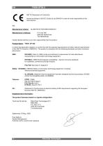
R&TTE Declaration of Conformity Issued according to ISO/IEC Guide 22 and EN45014 under the sole responsibility of the manufacturer We: Manufacturer’s Name: ALLIED DATA TECHNOLOGIES B.V. Manufacturer’s Address: hereby declare entirely on our own responsibility that the product: Product Name: TRON DF 560 to which this declaration relates is in conformity with the essential requirements and other relevant requirements of the R&TTE Directive (1999/5/EC). The product is compliant with the following standards and other normative documents: EMC: EN 55022, Class A (1998) Limits and methods of measurement...
Open the catalog to page 3
Allied Data Technologies
Open the catalog to page 4
Allied Data Technologies
Open the catalog to page 5
INTRODUCTION This manual describes how to use the DF56.0 modems. Two modems connect two computers over a longer distance through a telephone line. Data can be received from or sent to the other computer. In this way, contact can also be made with an external data base. Information in this data base can be read and if necessary, it can be received. This manual does not describe all steps that are necessary for data communication. The fact is, a number of transactions depend on the communication program that is used. The manual is mainly meant to give a survey of the application possibilities of...
Open the catalog to page 6
The equipment has been approved according to resolution 98/482/EC for European single terminal connection to the public telephone network (PSTN). Because of minor differences between the PSTNs in different countries, this approval does not it itself guarantee a correct link with every PSTN connection point. If you have any problems you should first contact your supplier. We do wish you lots of good connection with your TRON DF56.0. 1 DATACOMMUNICATION Computers can exchange (communicate) data (information) through a disk (floppy disk) through the connection of two serial ports, or through a network....
Open the catalog to page 7
Possible speeds are: 75, 300, 600, 1200, 2400, 4800, 7200, 9600, 12000, 14400, 16800, 21600, 24000, 26400, 28800, 31200 and from 33600 up to 56000 Bps. When the data bits, parity bits, and speed have been set on both sides (sender and receiver), a connection can be established. Information can then be exchanged. 1.2 ASCII and the meaning of data For the interpretation of received data, with most programs the ASCII table is used as a basis, in which each character has a unique bit combination. Sending text is relatively simple if both sides stick to this ASCII table. Control characters are also...
Open the catalog to page 8
We call the device that can carry out these conversions a modem (MOdulator / DEModulator). A modem’s function is therefore the conversion of digital (RS232C) into analogue signals and vice versa. However, with communication through a telephone line, a number of additional agreements are necessary: 1. It must be possible to establish a connection automatically (see paragraph 1.4). The analogue signal has to meet international agreement (see paragraph 1.5). 1.4 Setting up a connection Building up a data connection through the telephone line can be done in two different ways. 1. The easiest way...
Open the catalog to page 9
The ‘0’ has another pitch (frequency) than the ‘1’. The receiving modem recognises the two pitches that it receives and for its part, it forms again a digital signal out of the analogue signal. During the connection, the sender always transmits a tone. When at ease, the signal of the serial port is ‘1’ and the modem sends out the corresponding tone. We call this tone the CARRIER. The receiving modem knows that there is a connection with another modem by detecting this carrier. With FSK modulation, the pitch of the transmitted signal always has to be higher than the speed of the transmitted data....
Open the catalog to page 10
1.6 Originate and answer It is necessary to make agreements which modem uses which tone sets. For this purpose, the terms ‘originate’ and ‘answer’ are used. The modem that builds up the connection, sticks to the originate tones, the other one uses the answer tones. The originate modem sends as agreed with the low tones and the answer modem with the high tones. For a backchannel connection, this means that the originate modem sends with the low baudrate and the answer modem with the high baudrate. With a full duplex connection, both modems use the same baudrate and the tones for ‘0’ and ‘1’ are...
Open the catalog to page 11
2 INSTALLATION OF THE MODEM In this chapter, a description of the modem is given, the installation procedure will be explained and finally, it will be discussed how a connection can be built up step by step. 2.1 Description TRON DF56.0 At the front of the modem there are a number of lights that indicate (from the top down): the speed of the connection as well as the DTR level, TxD, RxD, CARRIER, On-line, AUTO ANSWER and POWER. At the bottom of the front, the Softkey is located. The speed LEDs have two functions: 1. When the modem is connected to another modem, they indicate the speed at which...
Open the catalog to page 12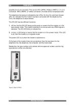
possible errors are corrected. This can be V42 (LAPM), V42bis or MNP 2, 3, 4, or 5 connection. With a MNP5- or V42bis connection, the data will be compressed also. The telephone line status is indicated by two LEDs: On-line (OL) and Auto Answer (AA). OL indicates that the modem has been connected with the telephone line. Then, the telephone is disconnected. The AA-LED has two different functions: 1. off-line: that the AA-LED being continuously on means that the modem is in the auto-answer mode. The modem switches to on-line as soon as a RING signal is detected. The AA-LED blinks to indicate this....
Open the catalog to page 13All Bausch Datacom catalogs and technical brochures
 M4 Product Family
10 Pages
 BasicBrochure RITTER Bausch
4 Pages
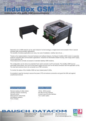
 InduBox GSM M4
2 Pages
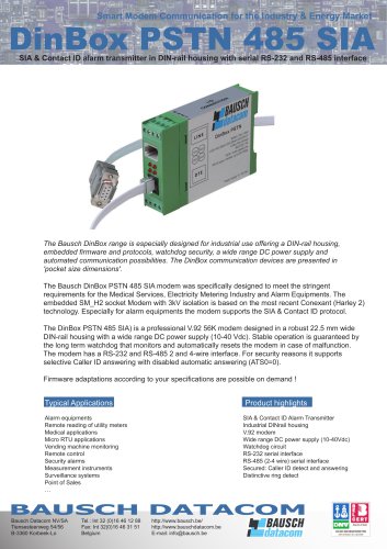 DinBox PSTN 485 SIA
2 Pages
 DinBox RTU SL
2 Pages
 Delta Logger
2 Pages
 Proxima PSTN 19 inch Rack
2 Pages
 Proxima GSM 19 inch rack
2 Pages
 DinBox GSM SL
2 Pages
 DinBox GSM M4
2 Pages
 DinBox 3G Router
2 Pages
 IBGSMIX_5_Eng
2 Pages
 IBGSMM4_New
2 Pages
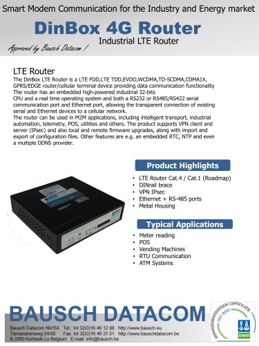 DB4GRouter_New
2 Pages
 Datasheet DINBox_M36
2 Pages
 DBRTUM36
2 Pages
 PULSARGPRSDS
2 Pages
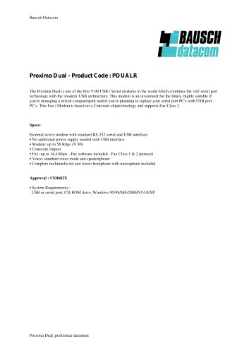 PDUALRDS_Eng_V1.1.pdf
1 Page
 Bausch MAC Products.PDF
4 Pages
 V56PCI2DS_V1.0_Eng
1 Page
 V56PC2RDS_Eng_V1.0
2 Pages
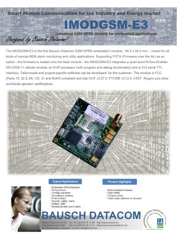 IMODGSM -E3
2 Pages
 Pulsar GPRS (PULSARGPRS)
2 Pages
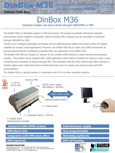 DinBox M36
2 Pages
 DinBox RTU (DB RTU)
2 Pages
 Meter reading communication
8 Pages
 DinBox GPRS SL (DB GPRS SL)
2 Pages
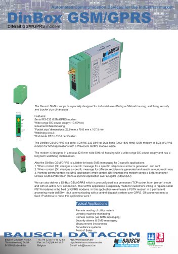 DinBox GSM/GPRS (DB GSMGPRS)
2 Pages
 InduBox GPRS (IB GPRS)
2 Pages
 Indubox GSM (IB GSM)
2 Pages
 Proxima ISDN Lite (P128ER)
2 Pages
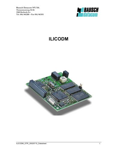 ILICODM
4 Pages
 SM_H2 SOCKET MODEM
2 Pages
 SM_H2
SM_H22 Pages
 SMD24XXL MODEM MODULE
2 Pages
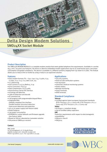 SMD24XX Socket Module
2 Pages
 Delta D32E25
1 Page
 Proxima GSM Rack
2 Pages
 Proxima Rack
2 Pages
 PDUALR
1 Page
 P33FU
P33FU2 Pages
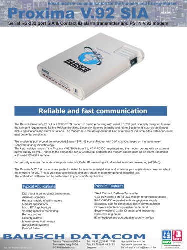 P56SIA
2 Pages
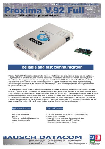 P56FUDS
2 Pages
 Vega 56 PC2 modem
2 Pages
 SMD2415V3
2 Pages
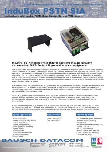
 InduBox PSTN
2 Pages
 V56PC2R
2 Pages
 PS2CD
PS2CD4 Pages
 DB PSTN
2 Pages


- Data logger
- Cloud-based software
- Industrial software
- Wireless datalogger
- Datalogger without display
- Industrial communication router
- Battery-powered datalogger
- Communication router with VPN
- EDM software
- Monitoring datalogger
- Cellular communication router
- Programmable datalogger
- 4G communication router
- DIN rail communication router
- Data management software
- LTE communication router
- RS232 communication router
- RS485 communication router
- M2M application communication router
- Industrial modem