
- Catalogs
- Baumer Group
- Force and strain sensors.


- Company
- Products
- Catalogs
- News & Trends
- Exhibitions
Force and strain sensors.
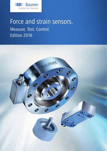
Force and strain sensors.
Baumer's 2016 edition on force and strain sensors presents a comprehensive range of products for measuring, testing, and monitoring applications. The document highlights the integration of established technology with innovative solutions to address diverse technical challenges.
The document categorizes products into several types of sensors and devices, each with specific applications and technical specifications:
- Load Cells (DLRx): Designed for static and dynamic applications, available in compression and tension/compression types, offering high precision and low noise signal processing.
- Strain Rings (DSRC): Used for strain measurement on tie bars and shafts.
- Strain Probes (DSRH): Suitable for strain measurement in holes.
- Strain Links (DSRT): Used for strain measurement on rigid structures.
- Piezo Electric Sensors: Include force sensors for dynamic measurement and cavity pressure sensors, providing high resolution and fast response times.
- Bridge Amplifiers (DABx) and Display Boxes (DDBF): For signal analysis and display of strain measurements.
- Charge Amplifiers (DACx): Used for analyzing piezoelectric sensors.
Each product type is detailed with technical specifications such as measuring range, characteristic curve deviation, output signal, protection class, and material composition. For instance, load cells have a characteristic curve deviation of 0.3% to 0.5% FS, with nominal forces ranging from 0.5 kN to 100 kN.
Applications include holding force control, force control during joining processes, and sheet thickness control, demonstrating the practical use of these sensors in industrial settings.
The document includes a glossary and explanations section to aid in understanding technical terms and concepts related to force and strain sensors.
The document outlines specifications for various load cells and strain rings used in mechanical engineering applications. Key specifications include:
- Protection Class: IP 65, ensuring protection against dust and water.
- Material: Stainless steel and corrosion-resistant steel for durability.
- Measuring Range: Various ranges from 0...500 N to 0...100000 N depending on the model.
- Output: Voltage output (0...10 V or ±10 V) and current output (4...20 mA).
- Combined Error: Typically 0.3% to 0.5% FS.
- Temperature Range: Operating temperature from -20 to +70 °C, storage temperature from -40 to +85 °C.
Additional technical data includes:
- Linearity and Hysteresis: Generally 0.3% to 0.5% FS.
- Non-repeatability: Less than 0.1% FS.
- Creep Error: Less than 0.2% FS after 30 minutes with full scale.
- Bridge Resistance: Full bridge 350 Ω.
- Isolation Resistance: Greater than 3 GΩ.
Details on connection and accessories include:
- Connector: 5-pin connector series M12 x 1.
- Cable Length: Standard 2 m, with options for 5 m and 10 m.
- Accessories: Connectors and cables are available but not included in delivery.
Strain rings are based on STRAIN-MATETM technology with strain gages, used for tension, compression, and torsion measurements in mechanical engineering and laboratory settings. They offer simple installation without surface preparation and are suitable for cyclical applications like clamping force measurements on presses.
Key features of the products include high accuracy and reliability for calibration and monitoring tasks, compact dimensions, robust construction, and suitability for both static and dynamic load applications.
Specifications for strain rings and probes include:
- Excitation voltage: Maximum 9 VDC, recommended 5 VDC.
- Signal polarity: Positive under tensile load when used with Baumer amplifiers.
- Rise time: Less than 1 ms on steel.
- Operating temperature range: -10 to +60 °C.
- Storage temperature range: -40 to +100 °C.
- Protection class: IP 54.
Mechanical and electrical characteristics include:
- Material: Aluminum anodized for the ring, stainless steel for protective foil.
- Bridge resistance: 350 Ω with a gage factor of K=2.00 ±0.5%.
- Bridge circuit: 2 x 1/4 bridge configuration.
- Output signal: 1 mV/V per 1000 µε.
- Combined error: Less than 1% FS.
- Linearity and hysteresis: Less than 0.5% FS.
- Repeatability: Less than 0.2% FS.
Guidelines for installation and usage include:
- Installation without surface preparation is possible.
- Strain rings are suitable for tension and compression measurements and cyclical applications.
- Reset function available to tare any arbitrary zero offset after mounting.
- Recommended to reset the bridge before each measuring cycle.
Various accessories and options are available for customization, including torque wrenches with adjustable and fixed settings, connecting cables with different lengths and connector types, and options for torsion measurement and telemetry system compatibility.
Strain probes are designed for measuring strain in deep holes, equipped with integrated amplifiers for voltage or current output. They are not suitable for static applications and require a reset before each cycle. Probes use STRAIN-MATETM technology for high accuracy.
Features include simple strain measurements in deep holes with a characteristic curve deviation of less than 1%, suitable for cyclical applications only, with an integrated amplifier providing voltage or current output. Electrical data includes a measuring range of ±1000 µε, with output signals of ±10 V or 4-20 mA. Mechanical data includes an amplifier enclosure made of anodized aluminum and a stainless steel tube.
Strain links are designed for static and dynamic applications, with a measurement range from ±100µε to ±750µε. They are suitable for use on rigid structures and can be used for force and weight measuring. Features include excellent repeatability, overload protection, and integrated reset circuits for automatic zero signal.
Bridge amplifiers convert mV signals from strain gage bridges into standardized output signals (V or mA). They are configured to work with Baumer sensors and are suitable for cyclic and static applications with reset, protection class IP 65, and designed for DIN rail installation.
This document provides technical specifications and operational details for various bridge amplifiers and display boxes used in strain gauge applications. It includes information on electrical and mechanical data, environmental conditions, and accessories.
Specifications for bridge amplifiers and display boxes include:
- Voltage and Current: Supply voltage ranges from 14 to 33 VDC, with current draw varying based on the model and application. Bridge excitation is typically around 7 to 9 VDC.
- Output Signals: Output signals are available in both voltage (±10 V) and current (4-20 mA) formats, with specific calibration and characteristic curve deviations provided for each model.
- Tare and Reset Functions: Tare accuracy and reset input specifications are detailed, including active and inactive voltage levels, pulse duration, and settle times.
- Frequency and Noise: Frequency range is typically up to 1000 Hz, with noise levels specified for different configurations.
Mechanical and environmental data include:
- Temperature Range: Operating temperatures range from -25 to +85 °C, with storage temperatures extending from -40 to +100 °C.
- Protection Class: Most devices are rated at IP 65, indicating dust-tight and water-resistant enclosures.
- EMC Compliance: Devices comply with EN 61000-6-2 for immunity and EN 61000-6-3 for emissions.
Details on accessories and connections include various connectors and cables, with specific part numbers provided for ordering, and electrical connections detailed with pin assignments for both control and sensor sides.
Display boxes are available in 2-channel and 4-channel configurations, with features such as peak value display, average value calculation, and integration with analysis software. They offer both analog and digital outputs, with selectable signal polarity and reset functions.
The InspectMaster software is included for data analysis, offering features like graph display, data saving, and export functions.
The document outlines the specifications for various Baumer products, including display boxes, piezoelectric sensors, and charge amplifiers. Key specifications include:
- PC requirements: Windows 2000, NT, XP with a minimum of 500 MHz and USB interface.
- Display box DDBF 4-SC: Features a 4-channel connection, measuring range of ±1000 µε, and a resolution of 1 µε. It includes a USB 2.0 connection and operates within a temperature range of +5 to +50 °C.
- Piezoelectric sensors: Various models such as DLPP 6MO, DLPP 8MO, DLPP 4MO, and DLPP 7MO are described, with capacities ranging from 250 N to 30 kN and operating temperature ranges from 0 to +200 °C.
- Cavity pressure sensors: Models like DPPC DS02.5 and DPPC DS04.0 are detailed, with a measuring range of 0 to 2000 bar and operating temperatures up to +200 °C.
Instructions on using the InspectMaster software for data display and analysis include displaying measurements in various units (µε, N, kN, t), graphical display, and data export capabilities, as well as reset functions via keypad or software.
Recommendations for operating conditions and environmental standards are provided, such as operating temperature ranges for different devices, protection classes like IP 40 and IP 65 for various components, and material specifications, including stainless steel for sensor enclosures.
The document lists accessories and connectivity options, including various sensor cables with different lengths and specifications, mounting accessories like special nuts and spacer tubes, and connection types such as BNC and Fischer connectors.
Details on charge amplifiers include models DACU 800 and DACU 820, with features like selectable ranges and RS 232 interface, and conversion of electrical charges from piezoelectric sensors to voltage outputs.
Catalog excerpts

Force and strain sensors. Measure. Test. Control. Edition 2016
Open the catalog to page 1
Force and strain sensors by Baumer combine tried and tested technology and sophisticated innovations.
Open the catalog to page 2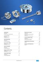
Introduction 1 Piezo Electric Sensors 8 Summary Force and Strain Sensors 1.4 Summary Force and Strain Sensors 8.3 Load Cells DLRx 2 Summary Cavity Pressure Sensors 8.9 Summary Load Cells 2.3 Charge Amplifiers DACx 9 Strain Rings DSRC 3 Summary Charge Amplifiers 9.3 Summary strain Rings 3.3 Supplementary Informations 10 Strain Probes DSRH 4 Product key 4.2 Glossary and Explanations 11 Summary Strain Probes 4.3 General 11.2 Strain Links DSRT 5 Summary Strain Links 5.3 Bridge Amplifiers DABx 6 Summary Bridge Amplifiers 6.3 Display Boxes DDBF 7 Summary Display Boxes 7.3
Open the catalog to page 3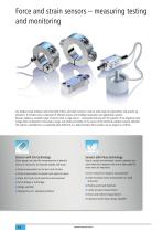
Force and strain sensors – measuring testing and monitoring Our product range embraces the entire field of force and strain sensors to meet a wide range of requirements and specific applications. It includes every component of efficient sensors and intelligent evaluation and application systems. Baumer supplies a complete range of sensors from a single source – universality that pays off. The question of the respective technology does not depend on the product range, but wholly and solely on the nature of the technical problem involved. Whether this calls for a bonded S/G, our patented press-fitted...
Open the catalog to page 4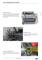
Load cell application examples Sheet thickness control Through sensors in the machine, the actual sheet thickness can be detected and the plunging depth of the upper tool automatically corrected. In this way, the machine achieves an angle quality independent of sheet thickness and with no loss of productivity or need for calibration. Holding force control Holding the sheet with needed force to make sure the sheet can moved as fast as possible without any slip or marks apply on the sheet. Force control at joining process In order to maintain best possible quality of the joining process, it’s elementary...
Open the catalog to page 5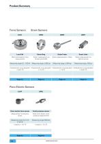
Product Summary Force Sensors Strain Sensors Load Cell Strain Ring Strain Probe Strain Links Strain measurement in holes Strain measurement on rigid structures Static and dynamic force measurement Measuring range 0,5…100 kN Strain measurement on tie bars and shafts Measuring range ±1000 µε Characteristic curve deviation Characteristic curve deviation Characteristic curve deviation Characteristic curve deviation < 0,3% FS < 1% FS < 1%FS < 0,8% FS Piezo Electric Sensors DLPP Piezo electric force sensor Cavity pressure sensor Measurement of dynamic forces Direct and indirect cavity pressure measurement...
Open the catalog to page 6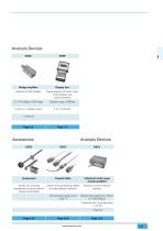
Analysis Devices DABx Bridge amplifier Signal analysis of strain rings, strain probes and extensometers 2 x 1/4 bridge or full bridge Current or voltage output Analysis Devices Coaxial Cable Industrial multi range charge amplifier Variety of mounting Sensor and connecting cables accessories for piezo electric for piezo electric sensors sensors and cables Temperature range up to +220 °C Analysis of piezo electric sensors Measuring range from 100 pC to 1'000'000 pC Characteristic curve deviation < 1% FS 1 channel
Open the catalog to page 7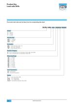
Product Key Load cells DLRx The correct order code must be taken from the corresponding data sheet. DLRx L00x.xxx.xxxxxx/xxxxx Output P = passive U Voltage = I = Current Housing Type L001 = miniature L002 = compact L003 = large Connection S80 = 4-pin connector series 712 W24 = 4-pin open cabel end 14C = 5-pin connector M12 x 1 Precision Category B = 0,3 % Characteristic curve deviation (Type L002, Type L003) C = 0,5 % Characteristic curve deviation (Type L001) Load Transmission CO = Compression TC = Tension/Compression Option C = top cover (Type L003) CL05 = 5 m cable length CL10 = 10 m cable...
Open the catalog to page 10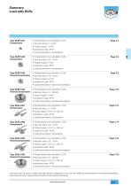
Summary Load cells DLRx Type DLRP L001 Compression • Characteristic curve deviation: 0,5% • Nominal force: 5...10 kN • Output signal: 1 mV/V • protection class: IP 67 • Load transmission: compression Type DLRP L002 Compression • Characteristic curve deviation: 0,3% • Nominal force: 0,5...10 kN • Output signal: 2 mV/V • protection class: IP 67 • Load transmission: compression Type DLRP L002 Tension/Compression • Characteristic curve deviation: 0,3% • Nominal force: 0,5...10 kN • Output signal: 2 mV/V • protection class: IP 67 • Load transmission: tension/compression Type DLRP L003 Tension/Compression...
Open the catalog to page 11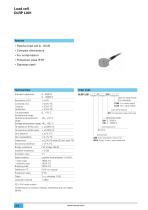
Load cell DLRP L001 • Passive load cell 0...10 kN • Compact dimensions • For compression • Protection class IP 67 • Stainless steel Order Code Technical Data Standard capacities Combined error Linearity Hysteresis CL05 5 m cable length CL10 10 m cable length Load transmission CO Compression (see drawing) Measuring range 250 0...5000 N 310 0...10000 N Temperature effect span < ±0,05% /K Zero balance Creep error Sensitivity tolerance Bridge resistance Isolation resistance Signal polarity – static load – dynamic load Breaking load Protection class Load cell material FS = Full scale output Combined...
Open the catalog to page 12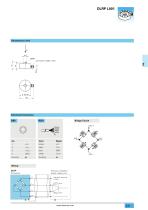
Electrical Connection brown black blue white Bridge Circuit SIG.+ Color Wiring DLRP Transducer Precision amplifier/ power supply unit +V S Stabilized operating voltage Gain + -
Open the catalog to page 13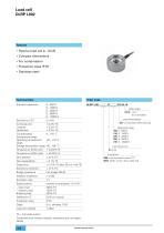
Load cell DLRP L002 • Passive load cell 0...10 kN • Compact dimensions • For compression • Protection class IP 67 • Stainless steel Order Code Technical Data Standard capacities Combined error Linearity Hysteresis cable length Load transmission CO Compression (see drawing) 150 210 220 250 310 B 0,3% Connection S80 4-pin connector series 712 W24 Cable, 4-wire, open cable end Creep error Sensitivity tolerance Bridge resistance Isolation resistance Signal polarity – static load – dynamic load Breaking load Protection class Load cell material FS = Full scale output Combined error contains linearity,...
Open the catalog to page 14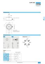
4 fixing screws M5, strength class 10.9 Installation torque 9 Nm Electrical Connection brown black blue white Bridge Circuit SIG.+ Color Wiring DLRP Transducer Precision amplifier/ power supply unit +V S Stabilized operating voltage Gain + -
Open the catalog to page 15All Baumer Group catalogs and technical brochures
 GT 5
GT 53 Pages
 AlphaProx
6 Pages
 OM70
OM702 Pages
 IFRM 12/18 series
230 Pages
 DPPC DS02.5
5 Pages
 CX series
22 Pages
 TCR6
TCR610 Pages
 TFR5
TFR56 Pages
 DLRx L003
2 Pages
 TFRN
TFRN9 Pages
 CTX
CTX6 Pages
 GCA5
GCA55 Pages
 TDP 0,2, TDPZ 0,2
5 Pages
 Ultrasonic sensors.
132 Pages
 CIP - Clean in place sensors
6 Pages
 Cable transducers
8 Pages
 SmartReflect® Transparent
2 Pages
 AlphaProx inductive sensors
6 Pages
 HMG 10 & PMG 10
6 Pages
 VeriSens® Vision Sensoren
26 Pages
 Digital industrial cameras
20 Pages
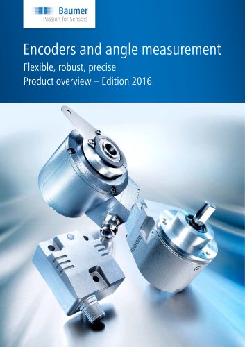 Encoders and angle measurement
100 Pages
 Innovative Sensor Solutions
72 Pages
 Capacitive sensors
60 Pages
 Inductive sensors.
200 Pages








- Digital imager
- Visible imager
- Angular encoder
- CMOS camera module
- Industrial camera module
- Pressure transmitter
- Incremental encoder
- Proximity switch
- Full-color camera system
- Tension/compression force transducer
- Level limit switch
- Steel load cell
- Cloud-based software
- Strain gauge force sensor
- Liquid level detector
- Level probe
- USB camera module
- Incremental rotary encoder
- Liquid level sensor