
Catalog excerpts
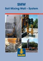
SMW Soil Mixing Wall – System 03/2012
Open the catalog to page 1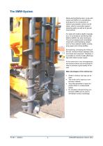
The SMW-System Mixing self-hardening slurry in-situ with native soil (SMW) is a cost-effective technique for the construction of walls for groundwater control (cut-off walls), walls for excavation support (retaining walls) as well as for ground improvement. For walls with shallow depths (typically 6 to 15 m) the Bauer Soil Mixing Wall Method (SMW) has been developed. The soil is loosened and immediately mixed with a self-hardening suspension by three adjacent slightly overlapping augers and mixing paddles. By loosening, conveying and mixing of the soil, minimum friction between rods and...
Open the catalog to page 2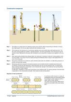
Construction sequence Excavation of a guide trench for collecting surplus slurry (trench width corresponding to diameter of mixing tool, depth approx. 50 cm) and align mixing tool with centreline of wall. Drill mixing tool into the ground in a continuous operation and concurrently inject self-hardening slurry. The two outer mixing paddles are rotated in opposite direction. The rate of penetration of the mixing tool and the volume of slurry delivered by the pump are controlled in such a way that no surplus slurry appears on the surface. After reaching the predetermined design depth, the...
Open the catalog to page 3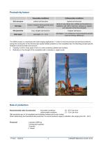
Productivity factors favourable conditions Unfavourable conditions Soil structure uniform soil structure layered soil structure Soil type loose to medium dense gravelly sand, silty sand dense to very dense soil, cobbles and boulders embedded in soil, stiff or hard soil, cohesive or organic soil (reduction of the final strength) Site geometry long, straight wall sections irregular wall layout Wall depth wall depth < 5 m (influence of non-productive periods such as moving, setting-up) The SMW process is a technique with wide-ranging applications. In order to avoid economical and technical...
Open the catalog to page 4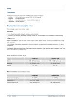
Slurry Components The slurry mix used in the construction of SMW panels consists normally of: Cement OPC or blast furnace cement CEM III/B 32,5 (typical) Bentonite Standard bentonite Additives (plasticizer, retarder or polymer additions) optional Admixtures (fly ash) optional Mix proportions and consumption values The mix design is governed by various factors: Application: Cut-off wall (permeability, strength, plasticity, erosion stability) Retaining wall (strength, permeability, plasticity of fresh mix - as precondition for the installation of reinforcement) Soil properties:...
Open the catalog to page 5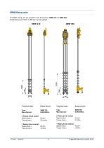
SMW-Mixing units The SMW mixing units are available in two dimensions: (SMW 370 and SMW 550). Wall thickness of 370 mm or 550 mm can be reached. Technical data: Rotary drives: Technical data: Rotary drives: Type Manufacturer Type Manufacturer 2 Rotary drives (outer) Speed (max.) Torque (max.) 2 Rotary drives (outer) Speed (max.) Torque (max.) 1 Rotary drive (central) Speed (max.) 64 rpm Torque (max.) 19 kNm 1 Rotary drive (central) Speed (max.) 68 rpm Torque (max.) 14 kNm © BAUER Maschinen GmbH, 2012
Open the catalog to page 6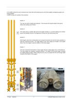
In the SMW method the soil is loosened and mixed with self hardening slurry with three slightly overlapping augers and mixing paddles. A SMW-mixing unit consists of four sections: Section 4: The rods end with a simple tube extension. This ensures the required depth of the panel, without the building up of friction. The mixing area is located right above the augers (Section 2). Counter-rotating and overlapping of the paddles ensures a homogeneous mixing over the whole panel area. Section 2: Short augers above the central pilots are moving the loosened soil and the slurry upwards, to ease the...
Open the catalog to page 7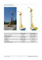
Base carrier (BG-series) 25415 Installed power Crowd pull Overall height SMW-unit (recommended) Panel depth (approx.) Operating weight (approx.) © BAUER Maschinen GmbH, 2012
Open the catalog to page 8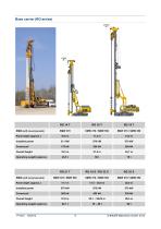
Base carrier (RG-series) 27400 Panel depth (approx.) Installed power Crowd pull Overall height Operating weight (approx.) Panel depth (approx.) Installed power Crowd pull Overall height Operating weight (approx.) SMW-unit (recommended) SMW-unit (recommended) © BAUER Maschinen GmbH,
Open the catalog to page 9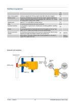
Additional equipment kW (ca.) Slurry mixing station minimum capacity 20 m³/h (e.g. batch mixer MAT SCC 20 or bigger) Delivery pump frequency controlled slurry pump with remote control, capacity depends on volume of panel and speed of mixing.(typically: 200 - 400 l/min, 12 – 15 bar, for instance EP 12-400 or EP 12-600) Agitator tank approx.3 - 5 m³ (as buffer for cement slurry) for cement and bentonite with screw conveyors Hydraulic backhoe for excavation of guide trench, maintenance of working platform, handling of backflow for conveying cement or bentonite slurry from the agitator to the...
Open the catalog to page 10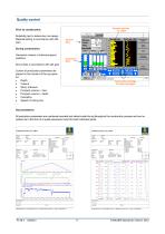
Quality control Pumpen quantity Pumpmengen vs. Depth über die Tiefe Prior to construction: Suitability test to determine mix design. Material testing in accordance with QA plan. General Allgemeine Data Daten During construction: Geometric checks of individual panel positions Equipment Geräte Data daten Slurry tests in accordance with QA plan Control of production parameters displayed on the monitor of the rig operator: Depth Volume Slurry pressure Pumped volume v. time Pumped volume v. depth Inclination Speed of mixing tool Inclinometer readings Neigungsmessung der On outer...
Open the catalog to page 11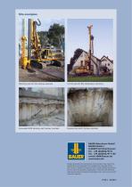
Site examples Retaining wall with RG, Sydney, Australia Cut-off wall with BG, Oberhausen, Germany Excavated SMW retaining wall, Sydney, Australia Exposed test shaft, Sydney, Australia BAUER Maschinen GmbH BAUER-Straße 1 D-86529 Schrobenhausen Tel. +49 (0)8252/97-0 Fax +49 (0)8252/97-1135 e-mail: BMA@bauer.de www.bauer.de Design developments and process improvements may require the specification and materials to be updated and changed without prior notice or liability. Illustrations may include optional equipment and not show all possible configurations. These and the technical data are...
Open the catalog to page 12All BAUER Maschinen GmbH catalogs and technical brochures
-
brochure BAUER
20 Pages
-
BAUER Dynamic Compaction
4 Pages
-
Ground Improvement
16 Pages
-
CSM- Cutter Soil Mixing
16 Pages
-
SMW Soil Mixing Wall ? System
12 Pages
-
VDW Double Head Drilling System
12 Pages
-
MC 64 Foundation crane
14 Pages
-
MC 96 Foundation crane
14 Pages
-
MC 128 Foundation crane
10 Pages
-
BD 50 Decanter
8 Pages
-
Well Drilling Unit
4 Pages
-
Ground Improvement
16 Pages
-
TBA 300 Deep Drilling Unit
8 Pages
-
TBA 200 Deep Drilling Unit
8 Pages
-
Exploration and Mining Equipment
12 Pages
-
MC Foundation Cranes
12 Pages
-
TR Depth Vibrators
4 Pages
-
BC 32 Trench Cutter
6 Pages
-
BG 36 H Rotary Drilling Rig
12 Pages
-
BG 20 H Rotary Drilling Rig
12 Pages
-
BG 12 H Rotary Drilling Rig
12 Pages


