
- Catalogs
- BAUER Maschinen GmbH
- Ground Improvement

Ground Improvement

Ground Improvement
Ground improvement is essential in construction projects with subsoil lacking sufficient bearing capacity. It provides an economical and fast method to enhance subsoil characteristics, avoiding deep foundations or extensive excavation.
- Minimizes environmental impact by avoiding excavation and soil disposal.
- Eliminates the need for groundwater lowering, reducing permit requirements and risks to adjacent structures.
- Adaptable to various soil conditions using natural materials for environmentally friendly solutions.
- Vibroflotation (VF): Suitable for non-cohesive and slightly cohesive soils, effective in fully saturated soils, and can handle high dynamic loads.
- Vibrodisplacement (VD): Applicable in mixed grained or cohesive soils, using coarse backfill to increase soil stiffness and facilitate drainage.
- Vibro Concrete Columns (VCC): Used in soft superficial deposits, providing high internal strength for light to medium structural loads.
Involves using a depth vibrator to compact soil, increasing density and reducing settlement risks through liquefying, densifying, and backfilling with granular material.
Creates stone columns in cohesive soils to increase bearing capacity, using a bottom-feed vibrator to displace soil and compact backfill material.
Used in low bearing capacity soils, providing high internal strength with pumped concrete, effective in cohesive and organic soils.
Ground improvement techniques like VF, VD, and VCC offer versatile solutions tailored to specific soil conditions and structural requirements.
Describes the construction and specifications of VCCs, including absorbing bending moments with column pairs and reinforcing for higher horizontal loads. The process involves placing a vibrator, lowering it to design depth, and forming the column shaft with continuous upward movement and constant concrete pressure.
Details technical specifications for equipment used in VCC construction, including depth vibrators and base machines, with parameters like centrifugal force, amplitude, speed, and power output.
Managed through the B-Tronic system, monitoring production data such as time, depth, concrete pressure, and energy consumption. Quality control involves load tests and cone penetrometer tests.
Recommends auxiliary equipment for efficient site operation, including loaders, pumps, compressors, and excavators, essential for processes like VF, VD, and VCC construction.
Catalog excerpts

Ground Improvement by Depth Vibrator 11/2012
Open the catalog to page 1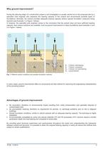
Why ground improvement? During the planning stage of a construction project a soil investigation is usually carried out on the proposed site by a specialist soils engineer who assesses the bearing capacity of the subsoil and recommends possible types of foundations. Normally, the subsoil provides adequate bearing capacity without special foundation measures being required (see Example 1 in Figure 1 below). If, however, the specialist soils engineer comes to the conclusion that the subsoil does not have sufficient bearing capacity, then various solutions are available, such as ground improvement...
Open the catalog to page 2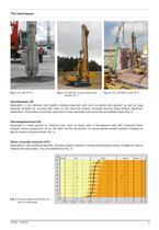
Fig. 3: VD with BF 12 and bottom feed vibrator TR 17 Vibroflotation VF Applicable in non-cohesive and slightly cohesive granular soils such as sands and gravels, as well as slag deposits. Suitable for carrying high loads on the improved subsoil, including dynamic loads without significant settlements. Particularly economical application in fully saturated soils below the groundwater table (Fig. 2). Vibrodisplacement VD Applicable in mixed grained or cohesive soils, such as sandy silts, to fine-grained soils with undrained shear strength values ranging from 20 to 100 kN/m² by the introduction...
Open the catalog to page 3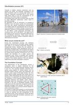
Vibroflotation process (VF) Granular or slightly cohesive sediments, such as gravels and sands, are generally considered to be ideal foundation soils for carrying high loads. It is, however, frequently overlooked that in their natural state these types of soil are characterised by an extremely non-uniform state of compaction. Surcharging these soils with structural loads can lead to large differential settlements, which result in structural damage. By application of the VF technique it is possible to transform such soil layers quickly and economically into soils with optimal load-bearing characteristics....
Open the catalog to page 4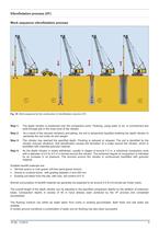
Vibroflotation process (VF) Work sequence vibroflotation process Fig. 10: Work sequence for the construction of vibroflotation columns (VF) The depth vibrator is positioned over the compaction point. Flushing, using water or air, is commenced and exits through jets in the nose cone of the vibrator. As a result of the induced vibrations and jetting, the soil is temporarily liquefied enabling the depth vibrator to penetrate the soil under its own weight. The vibrator has reached the specified depth. Flushing is reduced or stopped. The soil is densified by the vibrator induced vibrations. Soil densification...
Open the catalog to page 5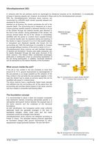
Vibrodisplacement (VD) In cohesive soils the soil particles cannot be rearranged by vibrational impulses as for vibroflotation. A considerable increase in bearing capacity can, however, be achieved in these soils by the vibrodisplacement process. With the vibrodisplacement technique stone columns are constructed by a BAUER depth vibrator specially adapted and equipped for this process. Assisted by air flushing, the vibrator penetrates the soil to the required depth. The surrounding soil is displaced as a result. Coarse granular backfill material is delivered directly to the tip of the vibrator...
Open the catalog to page 6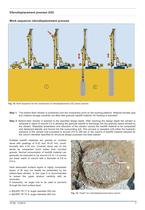
Vibrodisplacement process (VD) Work sequence vibrodisplacement process Fig. 13: Work sequence for the construction of vibrodisplacement (VD) stone columns Step 1: The bottom-feed vibrator is positioned over the compaction point on the working platform. Material transfer pipe and material storage container are filled with granular backfill material. Air flushing is activated. Step 2: Bottom-feed vibrator is lowered to the specified design depth. After reaching the design depth the vibrator is retracted in steps of around 0.5 m allowing the granular backfill to discharge into the granular space...
Open the catalog to page 7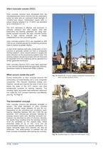
Vibro concrete column (VCC) Vibro concrete columns have developed from the vibrodisplacement stone columns and are particularly suited for soils with an undrained shear strength of 15 kN/m2 and above. Interbedded layers with cu values ranging between 8 to 15 kN/m² are permitted up to a thickness of 1 m. The VCC technique is effective and economic in primarily cohesive and also organic soils with particularly low bearing capacities. By using highquality pumped concrete, the vibro concrete column has a high internal strength and is largely independent from the surrounding soils. Vibro concrete...
Open the catalog to page 8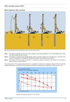
Vibro concrete column (VCC) Work sequence vibro concrete Fig. 17: Work sequence for the construction of vibro concrete columns (VCC) Step 1: The vibrator is placed over the VCC column position on the working platform. The concrete feeder pipe is filled with high-strength pumped concrete. Step 2: The vibrator is lowered to the specified design depth. Concrete is placed via a concrete pump. The base of the column is compacted and enlarged by repeated penetration and retraction of the vibrator. Step 3: The shaft of the VCC column is formed in a continuous upward movement of the vibrator and concrete...
Open the catalog to page 9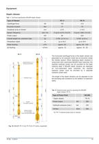
Equipment Depth vibrator Tab. 1: Technical specification BAUER depth vibrator Centrifugal force Eccentric moment Power output Overall weight incl. extension tube Penetration depth Speed / frequency Water flushing Air flushing The horizontal centrifugal forces of the depth vibrator are generated by an hydraulic motor and an eccentric inside the vibrator section. When deploying depth vibrators in conjunction with customised BAUER base machines, the required hydraulic power can be provided by the base machine itself. If BAUER depth vibrators are deployed on non-customised base machines, the required...
Open the catalog to page 10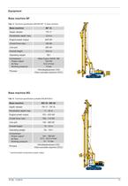
Equipment Base machine BF Tab. 3: Technical specification BAUER BF 12 base machine Base machine Depth vibrator Engine power output Line pull Overall height Operating weight Compressor Power output Air flow Working pressure Process 58 t Atlas Copco XAHS 186 104 kW 10.5 m³/min 12 bar Vibrodisplacement (VD) Vibro concrete columns (VCC) Base machine BG Tab. 4: Technical specification possible BAUER BG’s Base machine Depth vibrator Engine power output Line pull Overall height Operating weight Compressor Power output* Air flow Working pressure Process 104 - 186 kW 10.5 - 20.5 m³/min 10 - 12 bar Vibrodisplacement...
Open the catalog to page 11All BAUER Maschinen GmbH catalogs and technical brochures
 brochure BAUER
20 Pages
 BAUER Dynamic Compaction
4 Pages
 Ground Improvement
16 Pages
 SMW Soil Mixing Wall – System
12 Pages
 CSM- Cutter Soil Mixing
16 Pages
 SMW Soil Mixing Wall ? System
12 Pages
 VDW Double Head Drilling System
12 Pages
 MC 64 Foundation crane
14 Pages
 MC 96 Foundation crane
14 Pages
 MC 128 Foundation crane
10 Pages
 BD 50 Decanter
8 Pages
 Well Drilling Unit
4 Pages
 TBA 300 Deep Drilling Unit
8 Pages
 TBA 200 Deep Drilling Unit
8 Pages
 Exploration and Mining Equipment
12 Pages
 MC Foundation Cranes
12 Pages
 TR Depth Vibrators
4 Pages
 BC 32 Trench Cutter
6 Pages
 BG 36 H Rotary Drilling Rig
12 Pages
 BG 20 H Rotary Drilling Rig
12 Pages
 BG 12 H Rotary Drilling Rig
12 Pages


- Crane
- Mobile crane
- Drilling rig
- Lifting crane
- Rotary drilling rig
- Hydraulic drilling rig
- Mobile drilling rig
- Construction crane
- HMI
- Boom crane
- Hydraulic crane
- HMI with touch screen
- Pack unit
- Ethernet HMI
- Hydraulic grab
- Compact crane
- Multifunction drilling rig
- Civil engineering drilling rig
- Industrial HMI
- Construction drilling rig