
Catalog excerpts

USER MANUAL
Open the catalog to page 1
EN INTRODUCTION This user manual has been written by the equipment manufacturer and is an exclusive part of the product. The operations contained are directed to appropriately trained and qualified personnel. Its reading and conservation are recommended for future consultations. CONDITIONS OF USE BATSI® recommends that all devices, equipment and materials constituting the assembly should be installed in compliance with the European Directives 2006/42/EC (Machinery Directive), 2014/30/EU and subsequent modifications (low-voltage electrical equipment). For countries that are not part of the...
Open the catalog to page 2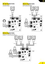
X-axis with output 1 connection example Double X-axis with outputs 1 and 2 connection example EP412J CONNECTIONS Double X-axis and double Y-axis with outuputs 1, 2, 3 and 4 connection example
Open the catalog to page 3
EN SOFTWARE CONFIGURATION The equipment can be configured by the user by means of software. It is possible to set the minimum and maximum actuation of each valve, the axes actuation centre, choose between a linear or logarithmic action ramp, opening and frequency limiter. The software will be supplied after the purchase of the equipment via telematic or direct download at the following link: www.batsi.eu/batsiconfigurator 1-. Connection: connect the device to the computer using a USB to MICROUSB cable. The operating system will detect it automatically; if the connection is correct, a green...
Open the catalog to page 4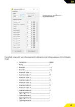
Once connected, you will see the equipment detected.
Open the catalog to page 5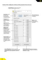
EN Preview of the configurator window and the parameters that can be set: Herramientas: the center point of the joystick is calibrated with this tool. Connection: select the input port from here once the equipment is connected to the PC. Frequency: the working frequency PWN for solenoid valves Center: sets the center of the X and Y axes by means of an analogue-todigital converter Once connected, the EP SERIES equipment is displayed Ramp: set here the ramp type: 1 for linear and 2 for logarithmic Maximum and Minimum: sets the maximum and minimum oil flow. Minimum valve opening to start oil...
Open the catalog to page 6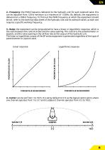
EN 2-. Frequency: the PWM frequency delivered to the hydraulic unit for each solenoid valve; this can be adjusted from 125Hz minimum to a maximum of 1250Hz. By default, the equipment is delivered at a 200Hz frequency. To find out the PWM frequency at which the equipment should be set, refer to the technical data sheet of the hydraulic unit and its solenoid valves, as each one requires a specific working frequency. 3-. Ramp: the equipment can be programmed to have a linear or logarithmic response, which is the ratio between the control stroke and the valve opening. The control is the...
Open the catalog to page 7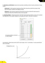
EN 5-. Maximum and Minimum: means the movement sensitivity, where it starts and where it stops acting. Maximum: it is the maximum opening of the valve, the point at which the valve is fully open and where it delivers the highest oil flow. Minimum: is the minimum opening of the valve, the point at which the valve starts to release oil, where the movement starts to be executed. 6-. Opening limiter: a fixed progressive and timed ramp (opening limiter) can be set to protect the equipment from sudden changes, e.g. changing the motor’s direction of rotation. An opening limiter can be set for each...
Open the catalog to page 8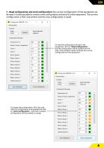
EN 7-. Read configuration and send configuration: the current configuration of the equipment can be read. It is also possible to create a new configuration and send it to the equipment. The current configuration is then overwritten and the new configuration is saved. To read the configuration stored in the equipment, click on “Read configuration”, and the configuration will be loaded into the cells. Cells marked in green indicate the current configuration of the equipment. To change the configuration, fill in the cells with the configuration to be applied and click on “Send configuration”....
Open the catalog to page 9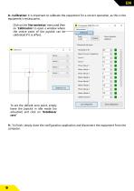
EN 8-. Calibration: it is important to calibrate the equipment for a correct operation, as this is the equipment’s resting point. Click on the ‘Herramientas’ menu and then on ‘Calibración’ to open a window where the centre point of the joystick can be calibrated if it is offset. To set the default zero point, simply leave the joystick in idle mode (no actuation) and click on “Establecer cero” 9-. To finish, simply close the configuration application and disconnect the equipment from the
Open the catalog to page 10
EiD Electrònics, SL Camí les comes, 23. Polígono Industrial 25123 Torrefarrera (Lleida) SPAIN Hereby declares that the product: Electronic controller Conforms with the provisions of the following EU Directives: EMC Directive 2014/30/EU According to following harmonized standards: EMC This product compiles with RoHS2 Directive 2011/65/EU Restriction on Hazardous Substances according to the standard: EN 50581:2012 Additional standards: This product does comply with the standards: ISO 10605:2008 Road vehicles – Test methods for electrical disturbances from electrostatic discharge ISO...
Open the catalog to page 11


