A200863
1 /2Pages

A200863
1 /2Pages
Catalog excerpts
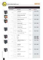
Control stations ComEx Standard Selection chart Wiring diagram Description Weight Order no. 1 pushbutton 0.33 kg 07-3511-10P74 0.36 kg 07-3511-10N84 0.40 kg 07-3511-10K34 0.35 kg 07-3511-10S94 0.35 kg 07-3511-10S04 0.35 kg 07-3511-10S14 1 NO + 1 NC incl. labels red, green, yellow, white 1 NOT/AUS Emergency Stop 1 NO + 1 NC marked NOT/AUS and Emergency-Stop 1 Mushroom Keyswitch 1 NO + 1 NC with key to reset 1 Selector switch 1 NO + 1 NC, 2 position with 2 stops 0 and I, latching 1 Selector switch 1 NO + 1 NC, 3 position with 3 stops I - 0 - II, latching 1 Selector switch 1 NO + 1 NC, 3 position with 3 stops I - 0 - II, momentary-contact 1 Lamp 0.35 kg red green yellow white 1 Mushroom Pushbutton, black 07-3511-10LRR 07-3511-10LGG 07-3511-10LYY 07-3511-10LWW 0.35 kg 07-3511-10P84 0.40 kg 07-3511-10K04 0.40 kg 07-3511-10K14 0.40 kg 07-3511-10K24 1 NO + 1 NC 1 Keyswitch 1 NO + 1 NC lockable in both positions 1 Keyswitch 03-0330-0189-08/08-BCS-200863/3 1 NO + 1 NC lockable in the pushed-in-position 1 Keyswitch 1 NO + 1 NC lockable in the initial position 30 200863_3_4.pmd 2 12.11.2010, 10:11
Open the catalog to page 1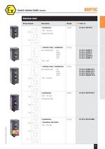
Control stations ComEx Standard Selection chart 1 Wiring diagram Description Weight Order no. 2 pushbuttons 0.50 kg 07-3512-10P74P74 1 NO + 1 NC each including key labels 2 3 1 indicator lamp, 1 pushbutton with indicated lamp 0.52 kg red green yellow white blue 07-3512-10LRRP74 07-3512-10LGGP74 07-3512-10LYYP74 07-3512-10LWWP74 07-3512-10LBBP74 4 1 NO + 1 NC 1 indicator lamp, 2 pushbuttons with indicated lamp 0.70 kg red green yellow white 07-3513-10LRRP74P74 07-3513-10LGGP74P74 07-3513-10LYYP74P74 07-3513-10LWWP74P74 5 1 NO + 1 NC each 6 3 pushbuttons 0.68 kg 07-3513-10P74P74P74 0.70 kg 07-3513-10P74P74N84...
Open the catalog to page 2All BARTEC catalogs and technical brochures
 HCDT
HCDT3 Pages
 HYGROPHIL F
4 Pages
 VI_4
VI_44 Pages
 PPA
PPA4 Pages
 MGA-nano
4 Pages
 CFPP
CFPP5 Pages
 FPA
FPA1 Page
 A/xx
A/xx4 Pages
 364923
1 Page
 127309
2 Pages
 R2810
R28102 Pages
 R300/301/302
8 Pages
 R2610
R26104 Pages
 R310/11/12/20
9 Pages
 R271
R2712 Pages
 309267_1
3 Pages
 VISC_4
4 Pages
 RVP_4
RVP_44 Pages
 DPA
DPA2 Pages
 CPA_4
CPA_44 Pages
 Switchgear and control gear
4 Pages
 A200865_7
2 Pages
 A200865_1
6 Pages
 A200663_4
1 Page
 A240847_1
2 Pages
 A280071
1 Page
 A200639_1E
4 Pages
 A200639
2 Pages
 321815_1E
3 Pages
 E246952_1E
2 Pages
 E301445_E
1 Page
 E246821_1E
2 Pages
 E246957_1E
4 Pages
 246903_1E
4 Pages
 E246904_2E
1 Page


- Panel PC
- Industrial panel PC
- Panel PC with touch screen
- LCD panel PC
- LCD screen
- Monitor with touchscreen
- Gas analyzer
- Automation software solution
- Chiller
- Monitoring analyzer
- Liquids analyzer
- Digital I/O
- Process software
- Panel-mount screen
- Automatic analyser
- Windows software
- IO module
- Windows panel PC
- Control software
- Touch screen tablet