
- Catalogs
- Barnes Group
- ISO Die Springs

ISO Die Springs
ISO Die Springs
RESSORTS SPEC compression springs are designed with a trapezoidal wire section to reduce stress and enhance longevity. They are produced under strict quality control by the BARNES Group's research team. Four load series are available, identified by color codes (Green, Blue, Red, Yellow), with detailed specifications available upon request.
Associated Spring Raymond Die Springs are crafted with an optimized wire cross-section for load balance and cycle life, adhering to ISO 10243 standards. Full technical specifications are available upon request.
- Superior Materials & Wire Profile: Made from high tensile chromium alloy steels, offering toughness, heat resistance up to 230°C, and optimal deflection.
- Dimensional Consistency: Ensures uniform performance and load accuracy.
- Longer Spring Life: Engineered for shock resistance and increased fatigue life by 30%.
- Excellent Deflection: Provides greater travel and load capacity.
- Hole Diameter (OD): The outside diameter of the spring.
- Rod Diameter (ID): The inside diameter of the spring.
- Free Length: The length before any load is applied.
- Preload: Reduction in free length due to assembly pressure.
- Operating Travel: The distance subtracted from the spring length after force application.
- Deflection: Change in spring length after force application.
- Solid Height: Length when fully compressed.
- Elastic Limit: Maximum stress without permanent deformation.
Use as many springs as possible to achieve the required load with minimal deflection, enhancing spring life and reducing failure risks. Consider the operating travel and select springs that operate efficiently within the required range. Calculate the number of springs needed based on total load requirements.
The document includes a detailed table for converting deflection percentages to compressed lengths across different duty levels (Light, Medium, Heavy, Extra Heavy).
It is recommended to use as many springs as the matrix can accommodate to achieve the desired load with minimal deflection. This approach increases the spring's lifespan and reduces the risk of breakage, machine downtime, production loss, and maintenance costs. The cost of a press tool spring is a small percentage of the total matrix cost, and saving a few cents on a spring can lead to significant labor and time costs.
Performance and Fatigue Monitoring
The faster a spring operates, the more its fatigue rate needs to be monitored. For slow cycles, excellent performance can be achieved with springs working at their maximum stroke. However, as the working speed increases, the spring's lifespan decreases.
Spring Selection Criteria
Springs suitable for presses or other components can be selected based on the required performance type: short, medium, or long term. For short and medium-term applications, use the deflections listed in the long-life columns. For long-term applications, use deflections based on optimal life. Recommended deflections for each spring according to desired performance are found on pages 6 to 13.
Load and Deflection Calculations
Another approach to selecting a spring is to consider the number of cycles the spring must endure, as specified on the matrix plot. Select springs in the appropriate load category for effective work at the required stroke. Calculate the number of springs needed by dividing the total desired load by the load provided by one spring. Round up the total number of springs for ideal performance.
Conversion Tables
The document provides conversion tables for length, rate, force, and torque, allowing for conversions between different units such as meters to inches, kilograms to pounds, and newtons to grams.
Load Deflection Table
The load deflection table provides detailed information on the load at 1 mm deflection, optimal life load, long life load, and maximum operating deflection for various spring sizes and catalog numbers. This data is crucial for selecting the appropriate spring for specific applications.
- Light Duty (ISO Colour Coded Green): This section lists components with their respective load deflection values for optimal life (25% of free length), long life (30% of free length), maximum operating deflection (35% of free length), and maximum deflection. The values are provided in Newtons (N) and millimeters (mm).
- Medium Duty (ISO Colour Coded Blue): Similar to the light-duty section, this part provides load deflection values for medium-duty components. The values are also tabulated for different deflection percentages.
- Hole Diameter (mm): Ranges from 25 mm to 305 mm.
- Rod Diameter (mm): Varies according to the component, with specific values provided for each catalog number.
- Free Length (mm): The free length of components is specified, which is crucial for calculating deflection percentages.
- Load Deflection Values: Detailed for each component, showing the load in Newtons at specific deflection percentages of the free length.
This document provides a detailed load deflection table for various spring models, identified by catalog numbers. The table includes specifications such as hole diameter, rod diameter, free length, and load at 1 mm deflection. It also outlines load and deflection values for optimal life (15% of free length), long life (17% of free length), and maximum operating deflection (20% of free length).
Key Sections:
- Specifications: Each spring is listed with its catalog number, hole diameter, rod diameter, and free length. These parameters are crucial for selecting the appropriate spring for specific applications.
- Load and Deflection Values: The table provides load values at different deflection percentages of the free length, which are critical for determining the spring's performance and lifespan.
- Design Considerations: The document includes a note on the potential for buckling in springs with squared, ground ends when compressed against parallel plates. It emphasizes the importance of using the specified hole sizes to prevent early spring wear or binding.
Important Notes:
- Load values are near solid and intended for design information only.
- Springs increase in diameter when compressed, necessitating correctly sized holes to avoid binding.
1. Spring Design and Installation: Ensure holes have flat bottoms and square corners for uniform stress distribution. Use a smooth rod for guidance to prevent buckling, and ensure proper alignment of guiding devices.
2. Temperature Considerations: The maximum service temperature for chromium alloy steel springs is 230°C. Heat can cause load loss and premature failure.
3. Deflection Limits: Avoid deflection beyond manufacturer recommendations to prevent early failure. Verify actual deflection during operation.
4. Spring Alteration: Altering springs by cutting or grinding can lead to failure. Maintain original design specifications.
5. Corrosion Prevention: Protect springs from corrosive elements to extend their lifespan.
Common Problems and Solutions
1. Spring Failure Causes: Often due to improper application or exceeding physical limits. Select appropriate springs for each application.
2. Guidance: Provide proper guidance to prevent buckling, especially if the free length exceeds four times the mean diameter.
Recommendations for Proper Application
1. Selection and Preloading: Include spring selection in early design stages and preload springs to prevent shock loading.
2. Environmental Safeguards: Protect springs from heat, corrosive atmospheres, and obstructions.
3. Maintenance: Perform regular maintenance and replace all springs at predetermined intervals.
4. Avoid Mixing Springs: Do not mix springs of different lengths or deflection ranges.
5. Consultation: Seek professional assistance for custom sizes and technical questions.
Catalog excerpts
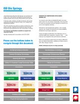
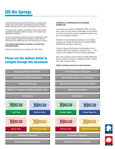
ISO Die Springs Associated Spring Raymond Die Springs are manufactured using a wire cross section developed to provide optimum balance between load carrying characteristics and cycle life. RESSORTS DE COMPRESSION EXTRA RAIDES NORMES ISO Produced under carefully controlled processes with special equipment developed by Barnes Group, Inc’s research and development facilities. Les ressorts extra raides de RESSORTS SPEC sont fabriqués à partir d’un fil à section trapézoidale, afin de garantir un niveau de contrainte minimum pendant le travail du ressort et une longévité maximale. All of the manufacturing steps are closely monitored by rigid quality controls, inspection and testing to ensure that the long service life engineered into every die spring is constant. Full technical specifications available on request from Associated Spring. Springs manufactured in accordance with ISO 10243. Please use the buttons below to navigate through this document: Fabriqués sur des équipements spéciaux, sous contrôle rigoureux par l’équipe de Recherche du Groupe BARNES, bénéficiant d’une longue expérience. Toutes les étapes de fabrication sont effectuées sous un contrôle qualité strict (inspection, mesures, tests, . . .) afin d’assurer une longévité et des performances optimales. Nous vous proposons quatre séries de charges différentes pour les mêmes dimensions, codifiées par quatre couleurs (Vert, Bleu, Rouge et Jaune). Détails techniques fournis sur simple demande. Die Spring Features & Benefits Common Die Spring Terminology Terminologie Commune des Ressorts Sélectionner un Ressort d’Outil de Presse Deflect' To Compress' Length Conversion Table Light Duty Medium Duty Charge Légère Charge Moyenne Heavy Duty Extra Heavy Duty Charge Forte Charge Extra Forte Proper Die Spring Application Utilisation Correcte du Ressort
Open the catalog to page 1
Die Spring Features & Benefits Superior Materials & Wire Profile Matériaux Supérieurs et type de fil • All Raymond die springs are made from high tensile strength chromium alloy steels. • Optimal wire cross section. • Spring ends are ground square. • Other raw materials are available for special conditions and environments. • Tous nos ressorts sont fabriqués à partir d’acier au Chrome Vanadium. • Fil trapézoïdal. • Extrémités rapprochées, meulées. • Autres matériaux disponibles pour des conditions et des environnements particuliers. • Dureté permettant de supporter des charges importantes. •...
Open the catalog to page 2
Common Die Spring Terminology Terminologie Commune des Ressorts HOLE DIAMETER This identifies the outside diameter (OD) of the die spring. Raymond die springs are available in eight different hole sizes matched to standard drill sizes. Each spring is made to fit in the hole, so the OD of the spring is actually less than the hole diameter. LOGEMENT Permet d’identifier le diamêtre extérieur (DO) du ressort d’outil de presse. Les ressorts en provenance de Raymond (USA) sont disponibles dans huit diamêtres de logement différents qui s’adaptent aux dimensions standards des forêts. Chaque ressort est...
Open the catalog to page 3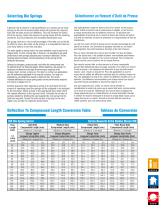
Sélectionner un Ressort d’Outil de Presse Une règle générale à observer dans le choix d’un ressort, est de toujours utiliser autant de ressorts que la matrice peut en adapter, ce qui fournira la charge recherchée avec une déflexion minimum. En découlera une augmentation de durée de vie du ressort et réduira les chances de rupture et d’arrêt de machines, de perte de production et d’augmentation de frais de maintenance. A general rule to observe in spring selection is to always use as many springs as the die will accommodate which will produce the required load with the least amount of deflection....
Open the catalog to page 4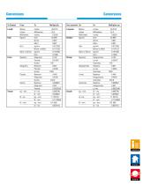
To Convert From To Multiply By Force Newtons Kilograms 0.102 Pour convertir De En Multiplier par Longueur Metres Inches 39.3701 Charge Newtons Kilogrammes 0.102
Open the catalog to page 5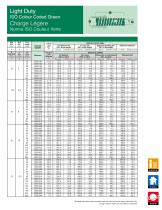
Light Duty ISO Colour Coded Green Charge Légère Norme ISO Couleur Verte Hole Dia. (mm) CATALOG NUMBER LOAD DEFLECTION TABLE For Long Life Maximum Operating Def. (30% of free length) (35% of free length) For Optimum Life (25% of free length) Load (N) Vie Optimale (25% Lo Libre) Charge (N) TABLEAU DE CHARGE Vie Longue Déflexion Maxi. de fonctionnement (30% Lo Libre) (35% Lo Libre) *Maximum Deflection Load (N) *Déflexion Maxi *Tabulated load values shown represent loads near solid and are for design information only. *Charge à hauteur solide, pour information uniquement.
Open the catalog to page 6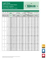
Light Duty ISO Colour Coded Green Charge Légère Norme ISO Couleur Verte Hole Dia. (mm) CATALOG NUMBER Load at 1 mm Def. (N) Charge à 1 mm Déflexion (N) For Optimum Life (25% of free length) Load (N) LOAD DEFLECTION TABLE For Long Life Maximum Operating Def. (30% of free length) (35% of free length) Load (N) TABLEAU DE CHARGE Vie Longue Déflexion Maxi. de fonctionnement (30% Lo Libre) (35% Lo Libre) *Maximum Deflection Load (N) *Déflexion Maxi *Tabulated load values shown represent loads near solid and are for design information only. *Charge à hauteur solide, pour information uniquement.
Open the catalog to page 7
Medium Duty ISO Colour Coded Blue Charge Moyene Norme ISO Couleur Bleue Hole Dia. (mm) CATALOG NUMBER Load at 1 mm Def. (N) Charge à 1 mm Déflexion (N) LOAD DEFLECTION TABLE For Long Life Maximum Operating Def. (25% of free length) (30% of free length) For Optimum Life (20% of free length) Load (N) TABLEAU DE CHARGE Vie Longue Déflexion Maxi. de fonctionnement (25% Lo Libre) (30% Lo Libre) *Maximum Deflection Load (N) *Déflexion Maxi *Tabulated load values shown represent loads near solid and are for design information only. *Charge à hauteur solide, pour information uniquement.
Open the catalog to page 8All Barnes Group catalogs and technical brochures
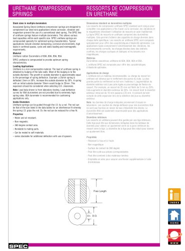 Urethane Compression Springs
8 Pages
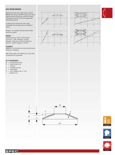 DIN 2093
5 Pages
 SURTIDOS EN CAJA
1 Page
 product selector
1 Page