- Catalogs
- BARDIANI VALVOLE S.p.a.
- GIOTTO TOP®
GIOTTO TOP®
1 /37Pages

GIOTTO TOP®
1 /37Pages
Catalog excerpts

Instruction, Use and Maintenance Manual CONTROL UNITS Bardiani Valvole S.p.A. via G. di Vittorio, 50/52 - 43045 Fornovo di Taro (PR) - Italy tel. +39 0525 400044 - fax +39 0525 3408 [email protected] - www.bardiani.com (Translation of the original instructions)
Open the catalog to page 1
MANUAL REVISION
Open the catalog to page 2
Safety, Warning and Mandatory Signs Operator training General safety warnings Giotto Top electrical connections 4 Checking / Unpacking / Lifting 5 Installation of the Giotto Top 6 Giotto Top Pneumatic connections 7 Troubleshooting 8 Cleaning 9 Disposal 10 Maintenance 10.1 10.2 Giotto Top Control unit Disassembly / Assembly of the Giotto Top 11 Valve complete with control unit 12 Warranty 13 Recommendations
Open the catalog to page 3
INTRODUCTION This “Instruction, Use and Maintenance Manual” has been drawn up expressly for expert technical personnel. Consequently any information which can easily be deducted from reading the text and/or examining the illustrations and/or drawings provided herein shall not be the object of further explanation. This “Instruction, Use and Maintenance Manual” forms an integral part of the control unit. Before proceeding with installation, use or maintenance of each type of control unit it is compulsory to read and understand this manual. This manual must be kept for all future reference When...
Open the catalog to page 4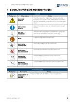
Safety, Warning and Mandatory Signs 1 Safety, Warning and Mandatory Signs SIGNALS Pictogram Description WARNING General OBLIGATION General SKILLED PERSONNEL NOTE ELECTRICAL CONNECTION ELECTRICAL DISCONNECTION PNEUMATIC CONNECTION PNEUMATIC DISCONNECTION Notes This tells the person in question that the operation described involves (when not performed in accordance with the relative safety regulations) the risk of personal injury. Special instructions must be followed to avoid injury to persons. Dismantling/Assembling and maintenance operations must be carried out by expert technicians only. Follow...
Open the catalog to page 5
Safety, Warning and Mandatory Signs Operator training All persons who have to work on the valve must be qualified to carry out the relative maintenance tasks. They must be informed as to the possible hazards involved and must observe all the safety instructions set out in this manual. Allow expert personnel only to work on the electrical components.
Open the catalog to page 6
General safety warnings Intended Use The control unit has been designed to control the pneumatically controlled process valves manufactured by Bardiani Valvole S.p.A.. It is possible to fit the Giotto Top with a maximum of three solenoid valves for controlling the process valve and up to a maximum of four inductive sensors, including an external one for controlling the position. For the electrical connections inside the control unit, there are three different configurations: • LED terminal block and As-i card: the LEDs indicate, in the presence of the relative inductive sensor, the status of...
Open the catalog to page 7
WARNING The control unit contains circuits classified as LOW VOLTAGE LIMITED ENERGY CIRCUIT. For correct use in North America dimension the protection circuits in accordance with Standard UL508A. WARNING ALWAYS make sure the electrical and pneumatic connections are NOT active when executing operations on the Giotto Top and that the power supply voltage is only 24 Vdc. Under normal circumstances (exposure time, eye pupils, viewing distance) it is assumed that the LEDs do not present any danger to eyes. In principle, however, please remember that intense light sources have a high potential of secondary...
Open the catalog to page 8
Technical data 3 Technical data CONTROL UNIT TECHNICAL DATA Weight from 0.55 Kg to 0.65 Kg depending on the configuration Casing material PA66 + PA6-GF30 (glass fibre reinforced nylon) Gaskets material Protection class Air supply and vent connections Electrical connections 7-pole connector, M12 5 pole connector, M12 8 pole connector, M12 12 pole connector Threaded fitting for cable gland PG11 or M20x1.5 2m cable with M12 connector and branch for flat cable or M12 connector and branch for flat cable Storage temperature SOLENOID VALVE APPLICATION CRITERIA Single Acting Valves Double Acting Valves...
Open the catalog to page 9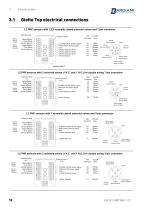
Technical data Giotto Top electrical connections 1,2 PNP sensors with 1,2,3 normally closed solenoid valves and 7-pin connector Solenoid valve 1 Sensor VALVE OPEN Sensor VALVE CLOSED Signal (Black) 0Vdc (Blue) +24Vdc (Brown) Signal (Black) 0Vdc (Blue) +24Vdc (Brown) CLOSED VALVE Sensor signal OPEN VALVE Sensor signal 0Vdc +24Vdc Solenoid valve 1 +24Vdc Solenoid valve 2 +24Vdc Solenoid valve 3 +24Vdc Sensors (Blue) (White) (Brown) (Purple) (Black) (Red) (Gray) Sensor signal VALVE OPEN Sensor signal VALVE CLOSED 1,2 PNP sensors with 2 solenoid valves (1 N.C. and 1 N.O.) for double acting 7-pin...
Open the catalog to page 10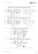
Technical data 1,2,3 PNP sensors with 1,2,3 normally closed solenoid valves and 8-pin connector Solenoid valve 1 Sensor VALVE OPEN Sensor VALVE CLOSED Solenoid valve 2 UPPER LIFT Sensor signal Signal (Black) 0Vdc (Blue) +24Vdc (Brown) Signal (Black) 0Vdc (Blue) +24Vdc (Brown) CLOSED VALVE Sensor signal OPEN VALVE Sensor signal 0Vdc +24Vdc Solenoid valve 1 +24Vdc Solenoid valve 2 +24Vdc Solenoid valve 3 +24Vdc Sensors COLOR PIN Connector Wire (8) (White) (Pink) (Blue) (Gray) (Green) (Yellow) (Brown) Sensor signal VALVE OPEN +24Vdc Solenoid valve 3 +24Vdc Solenoid valve 2 Sensor signal VALVE CLOSED...
Open the catalog to page 11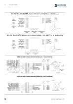
Technical data AS-i 360° Board 1,2,3,4 PNP sensors with 1,2,3 normally closed solenoid valves Sensor VALVE OPEN (DI0) Sensor VALVE CLOSED (DI1) Sensor LOWER LIFT (DI3) Sensor UPPER LIFT (DI2) Signal (Black) 0Vdc (Blue) +24Vdc (Brown) AS-i - (Blue) AS-i + (Brown) Signal (Black) 0Vdc (Blue) +24Vdc (Brown) Signal (Black) 0Vdc (Blue) +24Vdc (Brown) Signal (Black) 0Vdc (Blue) +24Vdc (Brown) AS-i 360° Board 1,2 PNP sensors with 2 solenoid valves (1 N.C. and 1 N.O.) for double acting Sensor VALVE OPEN (DI0) Sensor VALVE CLOSED (DI1) Sensor LOWER LIFT (DI3) Sensor UPPER LIFT (DI2) Signal (Black) 0Vdc...
Open the catalog to page 12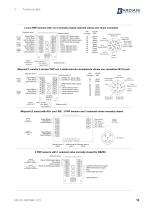
Technical data 1,2,3,4 PNP sensors with 1,2,3 normally closed solenoid valves and 12-pin connector Solenoid valve 1 Sensor VALVE OPEN Sensor VALVE CLOSED Sensor LOWER LIFT Signal (Black) 0Vdc (Blue) +24Vdc (Brown) Signal (Black) 0Vdc (Blue) +24Vdc (Brown) Signal (Black) 0Vdc (Blue) +24Vdc (Brown) UPPER LIFT Sensor signal LOWER LIFT Sensor signal CLOSED VALVE Sensor signal OPEN VALVE Sensor signal 0Vdc +24Vdc Solenoid valve 1 +24Vdc Solenoid valve 2 +24Vdc Solenoid valve 3 +24Vdc Sensors Sensor +24Vdc (brown) UPPER LIFT 0Vdc (Blue) (external) signal (black) COLOR PIN Wire Connettor External Sensor...
Open the catalog to page 13


