

B925

B925
This manual provides essential guidance for the installation, operation, and maintenance of Bardiani Valvole's mixproof valves. It is crucial for qualified technicians to review this document before handling the valves. The manual is updated regularly, with the latest version available on the manufacturer's website.
Various warning signs indicate potential hazards such as hand crushing, heavy loads, severe burns, and explosion risks. Mandatory signs include the use of protective gloves, hard hats, safety footwear, and suitable clothing. Maintenance operations should only be performed by skilled personnel.
The valves are designed exclusively for moving fluids and should not be used for other purposes or with unspecified fluids and pressures. They are not suitable for explosive or fire-risk environments unless certified for such use.
The valves have a maximum pressure of PN10 and are made from AISI 316L material. They are compatible with gasket materials like EPDM, FKM, and HNBR and comply with the PED 2014/68/EU directive.
Upon receipt, check the valve for transport damage and ensure it matches the order. Specific lifting methods are outlined for weights up to 25 kg, between 25 kg and 50 kg, and over 50 kg.
Installation should be performed by expert personnel, ensuring correct air pressure and power supply. Minimize stress from vibrations and thermal expansion, follow proper flow direction, and ensure adequate space for maintenance and correct valve orientation.
Before operation, inspect the valve by supplying air to the actuator and powering the valve. Open and close the valve several times to ensure proper functioning.
Common issues include external leaks due to worn gaskets or excessive pressure. Solutions involve replacing seals or using different elastomers.
Regular cleaning is necessary to maintain valve performance, following specific procedures for different components.
Dispose of the valve and its components in compliance with local regulations.
Maintenance includes general and scheduled tasks, requiring specific tools for disassembly and reassembly. Detailed procedures are provided for different valve models.
Includes 2D diagrams of various valve models and warranty information.
Issues such as too many active commands, difficulty in opening and closing, incorrect elastomer type for gaskets, incorrect actuator positioning, impurities in the actuator, and incorrect valve body positioning are identified. Solutions include replacing gaskets, correctly installing actuators, inspecting and maintaining actuators, and repositioning valve bodies.
Valves must be cleaned by experts using appropriate detergent concentrations and following manufacturer instructions. Protective gear is necessary due to potential burns from hot valves and piping. An internal washing cycle is required after installation or servicing, especially if welding has occurred.
At the end of its service life, the valve must be recycled according to local legislation, considering hazardous residues. Steps include ensuring the line is not in use, emptying and cleaning the line, disconnecting air and power supplies, and removing the valve from the system.
Maintenance should be performed by expert technicians with all utilities disconnected. Precautions include discharging fluid pressure and wearing protective gloves. Scheduled maintenance involves replacing valve and actuator gaskets periodically and checking for leaks. Original spare parts should be used for replacements.
A detailed list of tools and components for disassembly and reassembly of various valve models (B925, B925B, B925V, B925A) is provided, including descriptions and part numbers.
Instructions for adjusting the cam to ensure the sensor switches status correctly during valve operation.
Includes EC Declaration of Conformity and 2D diagrams for different valve models, ensuring compliance with relevant EC directives and standards.
Products are manufactured in compliance with technical specifications and directives, ensuring validity under specified conditions.
The warranty covers design, construction, and material defects for 12 months from the delivery date. Defects must be reported in writing within 8 days of detection, with supporting documentation. The warranty is limited to repair or replacement of defective products or components.
Elastomers and electrical components are excluded from the warranty. The warranty does not cover defects from buyer-provided designs, improper transportation, installation, use, maintenance, or storage, normal wear and tear, unauthorized repairs, or negligence. Bardiani Valvole S.p.A. is not liable for indirect or consequential damages.
Consultation of the "Instruction, Use and Maintenance Manual" is mandatory before installation, use, and maintenance. Illustrations are indicative and not binding. Buyers must assess product suitability before ordering. Bardiani Valvole S.p.A. reserves the right to update product information without notice.
Bardiani Valvole S.p.A., via G. di Vittorio, 50/52 - 43045 Fornovo di Taro (PR) - Italy. Tel: +39 0525 400044, Fax: +39 0525 3408, Email: [email protected], Website: www.bardiani.com
Catalog excerpts

Instruction, Use and Maintenance Manual MIXPROOF VALVE Bardiani Valvole S.p.A. via G. di Vittorio, 50/52 - 43045 Fornovo di Taro (PR) - Italy tel. +39 0525 - Fax 0525 3408 [email protected] - www.bardiani.com (Translation of the original instructions)
Open the catalog to page 1
MANUAL REVISION
Open the catalog to page 2
Safety,Warning and Mandatory Signs 1.1 Operator training General safety warnings Electrical connections Technical data Checking / Unpacking / Lifting Installation Operation Troubleshooting Cleaning Disposal Maintenance General maintenance Scheduled maintenance Tools useful for Disassembly/Reassembly Mixproof valve B925 - B925B Diverter 10.10 External Sensor Adjustment
Open the catalog to page 3
INTRODUCTION This “Instruction, Use and Maintenance Manual” has been prepared to provide guidance and recommendations to assist qualified skilled technicians in the understanding, running and maintenance orf the Products supplied. It forms an integral part of the Products supplied and must be read prior to any installation, operation and/or maintenance of all types of valves provided. This manual must be saved for future reference and be kept readily available at the unit. With regards to the use of valves compliant with EU Directive 2014/34/UE (ATEX), consultation of a specific manual is mandatory....
Open the catalog to page 4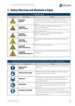
Safety,Warning and Mandatory Signs 1 Safety,Warning and Mandatory Signs WARNING SIGNS Pictogram Description WARNING General WARNING Hand crushing WARNING Heavy loads WARNING Severe burns WARNING Risk of explosions WARNING Loaded Spring Hazard Notes This tells the person in question that the operation described involves (when not performed in accordance with the relative safety regulations) the risk of personal injury. Exercise caution in executing the procedure Hand crushing hazard Never touch the moving parts if the actuator is supplied with complessed air Exercise caution in executing the procedure...
Open the catalog to page 5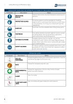
Safety,Warning and Mandatory Signs MANDATORY SIGNS (FOR THE OPERATOR IN CHARGE OF MECHANICAL MAINTENANCE) Pictogram Notes Special instructions must be followed to avoid injury to persons. OBLIGATION General PROTECTIVE GLOVES Use safety footwear to protect against injuries caused by falling objects during maintenance operations (particularly when dismantling parts). SUITABLE CLOTHING SAFETY GLASSES Protective gloves must be available for handling objects which could cause hand injuries or when there is the possibility of coming into contact with harmful substances.. Hard hats must be available...
Open the catalog to page 6
Safety,Warning and Mandatory Signs OPERATING SIGNS Pictogram Description PRESS PRESS (release) ELECTRICAL CONNECTION ELECTRICAL DISCONNECTION PNEUMATIC CONNECTION PNEUMATIC DISCONNECTION APPLICATION OF FOODSAFE GREASE APPLICATION OF FOODSAFE GREASE APPLICATION OF MULTIPURPOSE GREASE THREADLOCK APPLICATION ASSEMBLY / DISASSEMBLY SEQUENCE Use of a press Gradual release of the pressure force Electrical connection to the control unit (consult the relative instruction manual). Electrical disconnection from the control unit (consult the relative instruction manual). Connection of the air to the valve....
Open the catalog to page 7
Safety,Warning and Mandatory Signs 1.1 Operator training All persons who have to work on the valve must be qualified to carry out the relative maintenance tasks. They must be informed as to the possible hazards involved and must observe all the safety instructions set out in this manual. Allow expert personnel only to work on the electrical components.
Open the catalog to page 8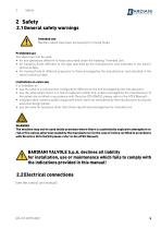
2 Safety 2.1 General safety warnings Intended use Bardiani valves have been exclusively for moving fluids. Prohibited use The valve must not be used: • for any operations different to those described under the heading “Intended Use”, • for handling fluids different to the type specified by the manufacturer and indicated in the valve's technical data; • for moving fluids at different pressures to those envisaged by the manufacturer and indicated in the valve's technical data. Limitations on valve use It is forbidden to: • use the valve in a construction configuration different to the one envisaged...
Open the catalog to page 9
Technical data 3 Technical data VALVE DATA Maximum pressure Maximum seal pressure Minimum pressure Storage temperature Material in contact with the product AISI 316L (1.4404). Check the resistance to corrosion in relation to products and detergents Gasket material in contact with the product EPDM, FKM, HNBR and other gaskets on request. Check compatibility with products and detergents Surface finish in contact with the product Ra 0.8 µm. Other finishes available on request Auxiliary washing circuit (B925B) connections ¼” BSP Male M14x1.5 Male for Ø8 pipe ½” Clamp VAPOUR BARRIER DATA Connectors...
Open the catalog to page 10
Checking / Unpacking / Lifting 4 Checking / Unpacking / Lifting 1. CHECK: - Check the valve show no signs of damage caused during transport and that it corresponds with the order; - Check the inside of the valve. 2. UNPACKING: The valve packaging is made up of cardboard, wood and plastic. The valve is mainly made up of metal materials. The gaskets are usually made from elastomers. Disposal must be in compliance with local legislation.
Open the catalog to page 11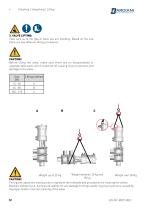
Checking / Unpacking / Lifting 3. VALVE LIFTING: Take care as to the type of valve you are handling. Based on the size there are two different lifting procedures. CAUTION! Before lifting the valve, make sure there are no disassembled or separate valve parts which could fall off causing injury to persons and damage to the valve. Size DN 15--50 65--80 100--125 CAUTION! The figures above are used purely to represent the methods and procedures for hoisting the valves. Bardiani Valvole S.p.A. declines all liability for any damage to things and/or injuries to persons caused by improper and/or incorrect...
Open the catalog to page 12
5 Installation 3 1. ELECTRICAL AND PNEUMATIC ENERGY SUPPLY - Use expert personnel for installation/uninstallation operations; - Check that the air pressure and quality are correct (see "Technical Data"); - Check the power supply to the control unit is correct (consult the relative instruction manual). 1 = Opening 2 = Top lift 3 = Bottom lift 2. REDUCING THE STRESS TO WHICH THE VALVE IS SUBJECTED: - Vibrations; - Thermal expansion of the piping; - Excessive welding; - Overload. CAUTION! The seal seats may become deformed or cause valve malfunctioning. 3. CORRECT DIRECTION OF FLOW: Flow in the...
Open the catalog to page 13All BARDIANI VALVOLE S.p.a. catalogs and technical brochures
 BBZS1 BBZS5
14 Pages
 BBZP
BBZP30 Pages
 BZAW3
BZAW38 Pages
 B935
B9358 Pages
 B915PMO
8 Pages
 BBZS5
BBZS560 Pages
 BBWP1
BBWP196 Pages
 GIOTTO TOP®
37 Pages
 ZVS
ZVS36 Pages
