
- Catalogs
- Badger Meter
- M5000


M5000

M5000
Catalog excerpts

M-Series® Mag Meter Model M-5000 IMPORTANT: This manual contains important information. READ AND KEEP FOR REFERENCE. IOM-832-01 (12-10) PN: 53400-832 Rev. 1 Installation & Operation Manual
Open the catalog to page 1
Model M-5000 Mag Meter Page ii (12-10)
Open the catalog to page 2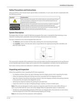
Installation & Operation Safety Precautions and Instructions Some procedures in this manual require special safety considerations. In such cases, the text is emphasized with the following symbols: Symbol Explanation When attached to the product, this symbol indicates a potential hazard. Review the documentation to determine the nature of the potential hazard and any required actions or precautions. Warning indicates the potential for severe personal injury, death or substantial property damage. Comply with the instructions and proceed with care. Caution indicates the potential for minor personal...
Open the catalog to page 5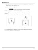
Model M-5000 Mag Meter • Storage: If the meter is to be stored, place it in its original container in a dry, sheltered location. Storage temperature ranges are: -40°F to 160°F (-40°C to 70°C). Rigging, Lifting and Moving Large Units When rigging, lifting or moving large units, follow these guidelines. DO NOT lift or move a meter by its amplifier, junction box or cables. Use a crane rigged with soft straps to lift and move meters with flow tubes that are between two inches and eight inches (50 mm and 200 mm). Place the straps around the detector body, between the flanges, on each side of the detector....
Open the catalog to page 6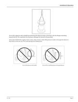
Installation & Operation Do not lift a detector with a forklift by positioning the detector body on the forks, with the flanges extending beyond the lift. This could dent the housing or damage the internal coil assemblies. Never place forklift forks, rigging chains, straps, slings, hooks or other lifting devices inside or through the detector's flow tube to hoist the unit. This could damage the isolating liner. Do not lift detector with forklift. (12-10) Do not lift or rig lifting devices through detector. Page 7
Open the catalog to page 7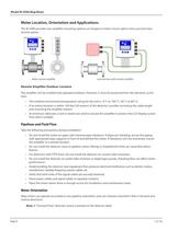
Model M-5000 Mag Meter Meter Location, Orientation and Applications The M-5000 provides two amplifier mounting options: an integral or meter mount option and a junction box/ remote option. Meter mount amplifier Junction box with remote amplifier Remote Amplifier Outdoor Location The amplifier can be installed and operated outdoors. However, it must be protected from the elements, as follows: • The ambient environment/temperature rating for the unit is -4° F to 140° F (-20° C to 60° C). • If an indoor location is within 100 feet (30 meters) of the detector, consider increasing the cable length...
Open the catalog to page 8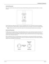
Installation & Operation Vertical Placement Mag meters perform best when placed vertically, with liquid flowing upward and meter electrodes in a closed, full pipe. Vertical placement allows the pipe to remain completely full, even in low flow, low pressure applications, and it prevents solids build-up, sediment deposit and accumulation on the liner and electrodes. Note: Carefully observe the “Forward Flow” label on the meter body and install the meter accordingly. Horizontal Placement M-5000 meters are equipped with an "Empty Pipe Detection" feature. If an electrode mounted in the pipe is not...
Open the catalog to page 9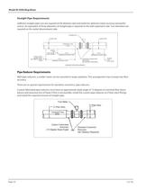
Model M-5000 Mag Meter Straight Pipe Requirements Sufficient straight-pipe runs are required at the detector inlet and outlet for optimum meter accuracy and performance. An equivalent of three diameters of straight pipe is required on the inlet (upstream) side. Two diameters are required on the outlet (downstream) side. FLOWMETER D (Pipe Size) D (Pipe Size) FORWARD FLOW ELBOW TEE GATE VALVE (FULLY OPEN) CHECK VALVE GLOBE VALVE BUTTERFLY VALVE PUMP 3xD 2xD MINIMUM STRAIGHT PIPE MINIMUM STRAIGHT PIPE 7xD MINIMUM STRAIGHT PIPE STANDARD CONCENTRIC REDUCERS (NO DISTANCE REQUIRED) ELBOW TEE ANY VALVE...
Open the catalog to page 10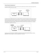
Installation & Operation Chemical Injection Applications For water line applications with a chemical injection point, install the meter upstream of the injection point. This eliminates any meter performance issues. Flow Meter FORWARD FLOW If a meter must be installed downstream of a chemical injection connection, the distance between the meter and the injection point should be between 50 and 100 feet (15 and 30 meters). The distance must be long enough to allow the water/chemical solution to reach the meter in a complete, homogeneous mixture. If the injection point is too close, the meter senses...
Open the catalog to page 11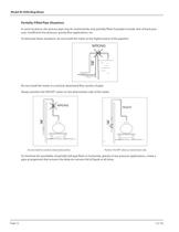
Model M-5000 Mag Meter Partially-Filled Pipe Situations In some locations, the process pipe may be momentarily only partially filled. Examples include: lack of back pressure, insufficient line pressure, gravity flow applications, etc. To eliminate these situations, do not install the meter at the highest point of the pipeline. WRONG RIGHT FLOW FLOW FLOW FLOW RIGHT WRONG FLOW FLOW WRONG RIGHT Do not install the meter in a vertical, downward flow section of pipe. Always position the ON/OFF valves on the downstream side of the meter. RIGHT WRONG RIGHT WRONG FLOW RIGHT FLOW FLOW FLOW FLOW FLOW WRONG...
Open the catalog to page 12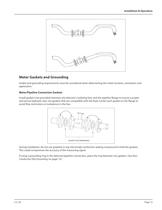
Installation & Operation Meter Gaskets and Grounding Gasket and grounding requirements must be considered when determining the meter location, orientation and application. Meter/Pipeline Connection Gaskets Install gaskets (not provided) between the detector's isolating liner and the pipeline flange to ensure a proper and secure hydraulic seal. Use gaskets that are compatible with the fluid. Center each gasket on the flange to avoid flow restrictions or turbulence in the line. GASKETS RECOMMENDED During installation, do not use graphite or any electrically conductive sealing compound to hold the...
Open the catalog to page 13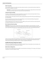
Model M-5000 Mag Meter Meter Grounding Process pipeline material can be either electrically conductive (metal) or not electrically conductive (made of or lined with PVC, fiberglass or concrete). Important: It is essential that the mag meter amplifier’s input ground (zero voltage reference) be electrically connected to the liquid media and to a good, solid earth ground reference. Conductive Pipe Grounding To achieve an adequate ground, the meter body MUST be electrically connected to the liquid media. The mag meter flanges are provided with grounding bolts for this purpose. If the pipe material...
Open the catalog to page 14All Badger Meter catalogs and technical brochures
 HR-E® LCD Encoder
2 Pages
 Recordall® Disc Meters
8 Pages
 RVL Series
8 Pages
 VN2000 Flow Meters
8 Pages
 Field Flow Calibrator
4 Pages
 Body Leakage Tester
2 Pages
 Measurable Results
12 Pages
 Blancett Overview
8 Pages
 Oil and Gas Market
8 Pages
 Automotive Products
12 Pages
 Model CB-30
2 Pages
 4000 series
2 Pages
 Test and Measurement
20 Pages
 Cox Exact Dual Rotor
8 Pages
 RTR
RTR2 Pages
 ADE®
ADE®2 Pages
 HR-E® LCD
2 Pages
 HR-E
HR-E2 Pages
 SRI990 Analog Positioner
2 Pages
 735 series
2 Pages
 GALAXY® Water Products
2 Pages
 Model M2000 Detector
2 Pages
 Model M2000 Amplifier
2 Pages
 Oval Gear Meter
1 Page
 M4000
M400036 Pages
 M3000
M300040 Pages
 M2000
M200060 Pages


