- Catalogs
- Badger Meter
- M4000
M4000
1 /36Pages

M4000
1 /36Pages
Catalog excerpts

M-Series® Mag Meter Model M-4000 Installation & Operation Manual IMPORTANT !!!! Read this manual before attempting any handling or installation of the meter. BadgerMeter, Inc. IOM-123-03 53400-123 Rev. 3 9-10
Open the catalog to page 1
Disclaimer The user/purchaser is expected to read and understand the information provided in this manual, follow any listed Safety Precautions and Instructions and keep this manual with the equipment for future reference. The information in this manual has been carefully checked and is believed to be entirely reliable and consistent with the product described. However, no responsibility is assumed for inaccuracies, nor does Badger Meter Incorporated assume any liability arising out of the application and use of the equipment described. Should the equipment be used in a manner not specied by Badger...
Open the catalog to page 2
SAFETY PRECAUTIONS and INSTRUCTIONS 8. Storage: If the meter is to be stored, place it in its original container in a dry, sheltered location. Storage temperature ranges are: -4°F to 158°F (-20°C to 70°C). Safety considerations are emphasized by the placement of safety symbol icons on the product or next to important text, pictures or drawings throughout this manual. The symbols are: Rigging, Lifting, Moving Large Units DO NOT lift or move a meter via its amplier, junction box or cables. When and where this symbol is attached to the product it indicates a potential hazard. It means that documentation...
Open the catalog to page 4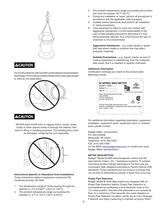
Do not lift a detector with a forklift via the detector body between theflanges.The housing could be dented and/or damage caused to internal coil assemblies. NEVER place forklift forks or rigging chains, straps, slings, hooks or other objects inside or through the detector flow tube for lifting or handling purposes. The isolating liner could be damaged, rendering the unit inoperable. Instructions Specific to Hazardous Area Installations These instructions apply to equipment covered by FM 1. The temperature range for fluids passing through the 2. The ambient temperature range surrounding the 3....
Open the catalog to page 5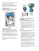
the electrode is again covered with uid, the error message disappears and the meter continues measuring. Amplier Mounting Conguration Options Two amplier-mounting conguration options are available to meet a variety of meter placement and environmental conditions. Meter Mount Conguration The Meter Mount conguration has the amplier mounted directly on the detector. This compact, self-contained conguration minimizes installation wiring. METER/AMPLIFIER LOCATION, ORIENTATION and APPLICATIONS Remote Amplier Outdoor Location The amplier can be installed and operated outdoors. However, protection from...
Open the catalog to page 6
This arrangement prevents solids build-up or sediment deposit or accumulation on the electrodes. 6. The ambient temperature range surrounding a remote junction box mounted to the detector is -4°F to 248°F (-20°C to 120°C.) Electrode Plane Pipelines and Fluid Flow Pipeline and uid ow conditions that should be avoided: Electrode Plane 1. Do not install the meter where extreme pipe vibrations exist. If vibrations are present, secure piping before and after the meter with appropriate pipe supports. If vibrations can’t be restrained, consider mounting the amplier remotely. 2. Avoid installing the...
Open the catalog to page 7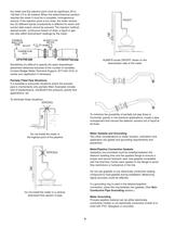
the meter and the injection point must be signicant; 50 to 100 feet (15 to 30 meters). When the water/chemical solution reaches the meter it must be a complete, homogeneous mixture. If the injection point is too close, the meter senses two (2) different liquids (conductivity is different for each) and correct data output cannot be assured. The injection method: spaced bursts, continuous stream of drips, a liquid or gas can also affect downstream readings by the meter. FLOW FLOW RIGHT ALWAYS locate ON/OFF valves on the downstream side of the meter Sometimes it’s difcult to specify the exact downstream...
Open the catalog to page 8
METER INSTALLATION PLANS and EXECUTION Plan meter layout, location and installation. During installation, remember these important points: To ensure proper unit operation, the mag meter impact ground (zero voltage reference) must be connected to the liquid media and to a good, solid earth ground. Perform grounding procedures after the meter is connected to the pipeline. 1. Heed all safety notications. 2. Select a detector location with room for installation and maintenance procedures. 3. Use proper lifting, rigging and moving procedures for large units. 4. Consider the meter environment; particularly...
Open the catalog to page 9
Mount Bracket/Amplier to Location 1. Position the bracket/amplier in the desired orientation. 2. Secure bracket/amplier to location. REMOTE MOUNT AMPLIFIER/DETECTOR WIRING Remote Mount Amplier The remote mount amplier has three chambers and ve wire ports. The Junction Box and Connections Chambers and wiring ports provide amplier openings for wire, conduit, tool and hand access to amplier terminal blocks. Detector to amplier wires connect in the Junction Box Chamber. Amplier AC power and customer signal wires attach in the Connections Chamber. · Suitably trained personnel shall perform all installation...
Open the catalog to page 10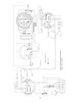
11 -5V -5V +5V +5V SHLD SHLD SHLD E2 E2 BACK ELECTRODE FOR CLASS 1 DIV 1 OR 2 FOLLOW NEC 501.4 AND 501.5 RED SLEEVE(FROM COIL) BLUE SLEEVE(FROM COIL) GROUND POST 18" MAX BETWEEN HOUSING AND CONDUIT SEAL L G N C1 C2 SHLD SHIELD CLEAR RED GREEN -5V +5V SHLD FOR CLASS 1 DIV 1 OR CLASS 1 DIV 2 FOLLOW NEC 504 SEAL 18" MAX OR SHIELD CLEAR RED SHIELD RED CLEAR BELDEN 8770 OR EQUIVALENT BETWEEN HOUSING AND CONDUIT SEAL 1 2 3 4 5 6 2 3 5 6 RED GREEN BLACK WHITE SHIELD 4 BELDEN 9155 OR EQUIVALENT C1 C2 SHLD 1 SHLD REMOTE MOUNT WIRING DIAGRAM CLASS 1 DIV 1, ZONE 1 ADD JUMPER TO CONNECT SHIELDED TERMINALS...
Open the catalog to page 11
NOTE: Plastic cover must be reattached to maintain hazardous location rating. 3. Strip the cable jacket back 2 inches (50mm). 4. Strip the 4 wires back ¼ inch (6mm). 5. Thread wires through the proper cable access. Connect the wires to the compression style screw terminals of the Detector Junction Box. WHITE BLACK PINK SHIELD CLEAR RED GREEN E1 OR 1.0 / 0.5 mm 2 BELDEN 8770 OR EQUIVALENT SHIELD RED CLEAR 18 AWG OR 1mm2 RED GREEN BLACK WHITE SHIELD SEAL EP E1 E2 SHLD -5V +5V SHLD BELDEN 9155 OR EQUIVALENT ELECTRODE WIRES CONDUIT SEAL LOCATED AT ENCLOSURE ENTRY PER 505.18 Red to terminal labeled...
Open the catalog to page 12All Badger Meter catalogs and technical brochures
 HR-E® LCD Encoder
2 Pages
 Recordall® Disc Meters
8 Pages
 RVL Series
8 Pages
 VN2000 Flow Meters
8 Pages
 Field Flow Calibrator
4 Pages
 Body Leakage Tester
2 Pages
 Measurable Results
12 Pages
 Blancett Overview
8 Pages
 Oil and Gas Market
8 Pages
 Automotive Products
12 Pages
 Model CB-30
2 Pages
 4000 series
2 Pages
 Test and Measurement
20 Pages
 Cox Exact Dual Rotor
8 Pages
 RTR
RTR2 Pages
 ADE®
ADE®2 Pages
 HR-E® LCD
2 Pages
 HR-E
HR-E2 Pages
 SRI990 Analog Positioner
2 Pages
 735 series
2 Pages
 GALAXY® Water Products
2 Pages
 Model M2000 Detector
2 Pages
 Model M2000 Amplifier
2 Pages
 Oval Gear Meter
1 Page
 M5000
M500044 Pages
 M3000
M300040 Pages
 M2000
M200060 Pages


- Control valve
- Flowmeter
- Volume flow monitor
- Pneumatic valve
- Liquid flow monitor
- Threaded valve
- Regulating valve
- Flange valve
- Angular encoder
- Data logger
- Electric valve
- Waterproof flow meter
- Gas flow monitor
- Pneumatically-operated valve
- Stainless steel flow monitor
- Spectrometer
- Piston actuator valve
- Portable tester
- Industrial flow monitor