- Catalogs
- B9Creations
- Step 5 - Final Assembly (1 of 2)
Step 5 - Final Assembly (1 of 2)
1 /10Pages
Step 5 - Final Assembly (1 of 2)
1 /10Pages
Catalog excerpts

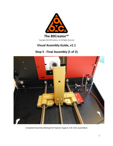
The B9Creator™ Copyright 2013 B9Creations, LLC All Rights Reserved Visual Assembly Guide, v1.1 Step 5 - Final Assembly (1 of 2) Completed Assembly (Mating the Projector Support, X & Z Axis assemblies)
Open the catalog to page 1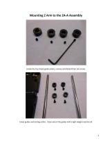
Locate the four linear guide collars, remove and discard their set screws. Linear guides and locking collars. Clean and oil the guides with a light weight machine oil.
Open the catalog to page 2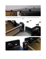
Insert the screw from the backside of the ZA-A assembly. Screw them (just a few threads) into the collars.
Open the catalog to page 3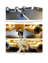
Align the Z Decoupler Frame over the nut as shown. NOTE: The frame should easily slide "side to side" on the nut but with almost no "up down" freedom. Gently place the ZA-B assembly over the Z Decoupler Frame, engaging the Z Decoupler Mount as shown.
Open the catalog to page 4
Insert the first linear guide rod. Once the rod is flush with the top and bottom opening, tight the upper and lower collar locks to fix it in place. 5
Open the catalog to page 5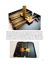
Repeat on the other side. IMPORTANT! Turn the lead screw by hand to ensure the table arm moves easily and smoothly throughout the entire range. If movement seems to "stick", etc. make sure the linear bearings and lead screw nut are lubricated with lightweight machine oil. Also, you may need to loosen the 8 ZA-A assembly screws to allow the table arm fixture to "relax" and better align with the rods. Retighten the inner 6 screws first and then the outer 4 screws. Do not over tighten the outer four screws, just do so enough to secure the 4 linear bearings are trapped. This is a critical step in...
Open the catalog to page 6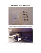
Once aligned, the ZA, XA & PS assemblies are secured using the SA15 hardware. When aligning the three assemblies ensure the Z Axis Stepper Motor mates correctly with the Z Axis Lead Screw.
Open the catalog to page 7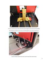
Here you can see the four SA15 screws that pass through ZA, XA and into the PS assembly. The XA Power and home sensor wires are fed through the access hole to the ZA area. Connect the Build Table Home sensor and the lower limit switch wiring. 8
Open the catalog to page 8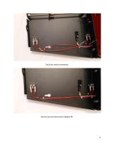
Top limit switch connected. Zip ties secured and excess clipped off.
Open the catalog to page 9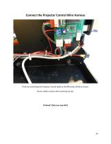
Connect the Projector Control Wire Harness Finish by connecting the Projector Control cable to the B9Creator Shield as shown. Secure cables in place with remaining zip ties. Finished! (Only one step left!)
Open the catalog to page 10All B9Creations catalogs and technical brochures
 B9Creator Technology
2 Pages
 Step 6 - Final Assembly (2 of 2)
27 Pages
 Step 3 - Z Axis (ZA-A) Assembly
13 Pages
 Step 2 - X Axis (XA) Assembly
31 Pages
 B9Clean
2 Pages
 B9 Core 530
1 Page
 B9 Scan 350
1 Page
 B9Creator v1.2
1 Page
 B9 Core 550
1 Page
 Black Resin
3 Pages
 Gray Resin
3 Pages


- Additive manufacturing machine
- Industrial 3D printer
- Plastic additive manufacturing machine
- 3D scanning system
- Prototyping 3D printing machine
- High-speed 3D printer
- 3D printing resin
- Curing system
- Medical 3D printing machine
- Dental additive manufacturing machine
- UV curing system
- Polymer 3D printing resin
- Resin 3D printer
- Industrial 3D printing resin
- DLP 3D printer
- Black 3D printing resin
- Cleaning station
- Red 3D printing resin
- Green 3D printing resin
- Yellow 3D printing resin