
- Catalogs
- B9Creations
- Step 4 - Z Axis (ZA-B) Assembly


Step 4 - Z Axis (ZA-B) Assembly

Step 4 - Z Axis (ZA-B) Assembly
Catalog excerpts

The B9Creator™ Copyright 2013 B9Creations, LLC All Rights Reserved Visual Assembly Guide, v1.1 Step 4 - Z Axis (ZA-B) Assembly Completed ZA-B (Build Table & Arm) Assemblies 1
Open the catalog to page 1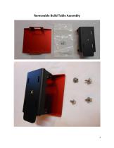
Removable Build Table Assembly
Open the catalog to page 2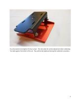
You only need to hand tighten the four screws. The slots allow for vertical adjustment when calibrating the table against the bottom of the vat. They will be fully tightened during that calibration procedure.
Open the catalog to page 3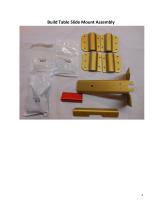
Build Table Slide Mount Assembly
Open the catalog to page 4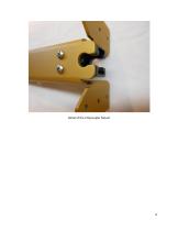
Detail of the Z Decoupler Mount
Open the catalog to page 6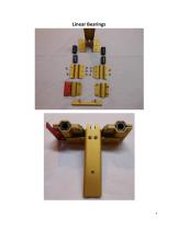
Linear Bearings
Open the catalog to page 7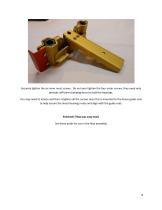
Securely tighten the six inner most screws. Do not over tighten the four outer screws, they need only provide sufficient clamping force to hold the bearings. You may need to loosen and then retighten all the screws once this is mounted to the linear guide rods to help ensure the linear bearings mate and align with the guide rods. Finished! (That was easy too!) Set these aside for use in the final assembly.
Open the catalog to page 8All B9Creations catalogs and technical brochures
 B9Creator Technology
2 Pages
 Step 6 - Final Assembly (2 of 2)
27 Pages
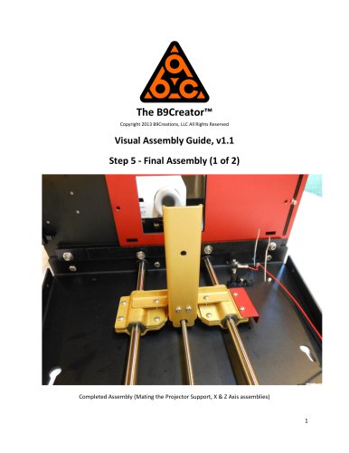 Step 5 - Final Assembly (1 of 2)
10 Pages
 Step 3 - Z Axis (ZA-A) Assembly
13 Pages
 Step 2 - X Axis (XA) Assembly
31 Pages
 B9Clean
2 Pages
 B9 Core 530
1 Page
 B9 Scan 350
1 Page
 B9Creator v1.2
1 Page
 B9 Core 550
1 Page
 Black Resin
3 Pages
 Gray Resin
3 Pages




- Industrial 3D printer
- 3D scanning system
- Plastic additive manufacturing machine
- Prototyping 3D printing machine
- High-speed 3D printer
- 3D printing resin
- Curing system
- Resin 3D printer
- Medical 3D printing machine
- Dental additive manufacturing machine
- UV curing system
- Polymer 3D printing resin
- Industrial 3D printing resin
- DLP 3D printer
- Black 3D printing resin
- Cleaning station
- Red 3D printing resin
- Green 3D printing resin
- Yellow 3D printing resin