- Catalogs
- B9Creations
- Step 3 - Z Axis (ZA-A) Assembly
Step 3 - Z Axis (ZA-A) Assembly
1 /13Pages

Step 3 - Z Axis (ZA-A) Assembly
1 /13Pages
Catalog excerpts

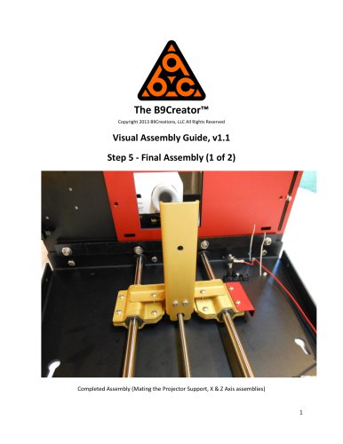
The B9Creator™ Copyright 2013 B9Creations, LLC All Rights Reserved Visual Assembly Guide, v1.1 Step 3 - Z Axis (ZA-A) Assembly Completed ZA-A (Vertical Slide Support) Assembly 1
Open the catalog to page 1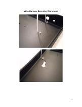
Wire Harness Restraint Placement
Open the catalog to page 2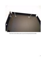
These three zip ties will be used to secure the wiring during final assembly.
Open the catalog to page 3
Limit Switches SA-08 and switches. These switches cut power should the build table attempt to exceed proper limits.
Open the catalog to page 4
Upper limit switch in place, note nylon standoff placement and orientation of switch lever. Lower limit switch in place.
Open the catalog to page 5
Limit switches with Power Cable 3 routed and connected.
Open the catalog to page 6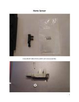
Home Sensor Z Axis (Build Table) Home switch and screw assembly.
Open the catalog to page 7
Home switch mounted.
Open the catalog to page 8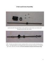
Z Axis Lead Screw Assembly Lead screw with Z Decoupler Mount, Fame and Nut (on lead screw), two miniature ball bearings and two shaft collar clamps. NOTE: The lead screw diameter has been machined smaller on each end to allow the ball bearings to slide on. This smaller diamter on one end goes further up the screw than the other end. The long end goes "down" (left side in this photo). Be sure the orientation of all parts match the above image.
Open the catalog to page 9
"down" end, note bearing orientation and how far the bearing will slide up the screw. "up" end, note bearing orientation and how it is limited on how far down it can slide. Mounting the lead screw: "up" end - Adjust the collar such that the top end of the lead screw extends ~2mm beyond the bracket and tighten it down securely on the lead screw
Open the catalog to page 10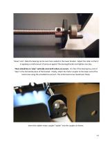
"down" end - Note the bearing can be seen here seated in the lower bracket. Adjust the collar so that it is applying a small amount of pressure against the bearing/bracket and tighten securely. There should be no "play" vertically once both collars are secure. It is fine if the bearing has a bit of "slop" in the horizontal plane of the bracket. Finally, attach the motor coupler to the lower end of the lead screw using the provided hex wrench. The entire lead screw should spin freely. Insert the rubber motor coupler "spider" into the coupler as shown.
Open the catalog to page 11
This will eventually be mated with the Z-Axis motor which was mounted to the XA assembly. (Shown here for reference only.)
Open the catalog to page 12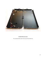
Finished! (That was easy!) This assembly will be used in the next, ZA-B assembly step.
Open the catalog to page 13All B9Creations catalogs and technical brochures
 B9Creator Technology
2 Pages
 Step 6 - Final Assembly (2 of 2)
27 Pages
 Step 5 - Final Assembly (1 of 2)
10 Pages
 Step 2 - X Axis (XA) Assembly
31 Pages
 B9Clean
2 Pages
 B9 Core 530
1 Page
 B9 Scan 350
1 Page
 B9Creator v1.2
1 Page
 B9 Core 550
1 Page
 Black Resin
3 Pages
 Gray Resin
3 Pages


- Additive manufacturing machine
- Industrial 3D printer
- Plastic additive manufacturing machine
- 3D scanning system
- Prototyping 3D printing machine
- High-speed 3D printer
- 3D printing resin
- Curing system
- Medical 3D printing machine
- Dental additive manufacturing machine
- UV curing system
- Polymer 3D printing resin
- Resin 3D printer
- Industrial 3D printing resin
- DLP 3D printer
- Black 3D printing resin
- Cleaning station
- Red 3D printing resin
- Green 3D printing resin
- Yellow 3D printing resin