Group: Azbil

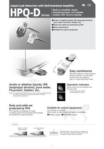
Catalog excerpts

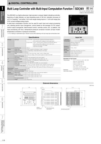
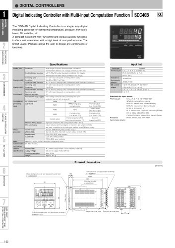
No. CP-SS-1861E Network Instrumentation Module Controller Module NX-D15/25/35 Overview Network Instrumentation Modules make optimal distributed configuration a reality. Distributed modules execute cooperative control using Ethernet connectivity. This instrumentation offers an excellent solution for productivity and energy conservation needs. A variety of input sampling cycles and input accuracy levels are available, depending on the model. • Sampling cycles: 100 ms, 200 ms, and 500 ms • Input accuracy: ±0.1 % FS and ±0.3 % FS Compact digital controllers with advanced functions can execute 2-loop or 4-loop control. • 2-loop control (with RSP) or cascade control (available soon), depending on the control mode • Heat/cool control using a combination of control outputs • Control output branching for multiple actuators • 6 LED indicators (standard), and additional LEDs depending on the model, provide abundant status information • 3-part structure for easy maintenance • Equipped with input/output broken line approximation for nonlinear processes. • 4 additional CT/DI/DO points optionally available • Logical operation processing for DI/DO and internal events • Data transfer function allows operation input/output between modules • Multi-loop cooperative control with supervisor module Control output can be selected from among transistor output, DC current, DC voltage output, and motor driver output (available soon). Optionally, 4 current transformer inputs, 4 digital outputs, or 4 digital inputs are also available. Since the SLP-NX Smart Loader Package can be connected via Ethernet, Network Instrumentation Modules can be set up and monitored over an Ethernet communications network. Features • Ethernet and RS-485 as standard features • Up to 4 control loops per module • Side connectors for reduced wiring • Support for reduced wiring daisy-chain connection and distributed layout • Full multi-range input for thermocouple, RTD, DC current, and DC voltage NX-D15/25/35 basic function block diagram PV inputs (1 to 4) 4 digital inputs (optional) • Thermocouple, RTD, DC current, and DC voltage input • Digital filter • Ratio/bias • Square root operation • Linear approximation* • Remote SP input • SP group selection • RUN/READY mode selection • AUTO/MANUAL mode selection • LSP/RSP mode selection • Latch release etc. Motor feedback (MFB) input* 4 current transformer (CT) inputs (optional) Other modules MV Control calculation component SP/PV/DEV/ RSP/MV AUTO/ MANUAL Broken-line approximation Broken-line approximation (1 loop, cascade control*) • Direct/reverse action • Heat/cool control • Event configuration • DC current • DC voltage • Transistor • Motor driver (transistor)* EV Ethernet protocol Communications input/output Fixed-value outputs* 1 to 8 • PID control (up to 4-loops) Data transfer between modules Communications input/output AUX Output limits RS-485 (3-wire) communications 4 outputs SP/PV/DEV/RSP/MV status/alarms 4 digital outputs (optional) Loader communications Power 24 Vdc 1 * Available soon SLP-NX Smart Loader Package
Open the catalog to page 1
Table 1. Input types and ranges
Open the catalog to page 6
■ Input sensor standards Gold-iron Chromel (ASTM E1751-00) ■ Behavior if a PV input error occurs Note: If DC current exceeds descriptions, intermittent circuit interruption may occur to protect circuits.
Open the catalog to page 7
Model Selection
Open the catalog to page 8
External Dimensions • Removal procedures (1) To unlock the terminal block, slide its lock lever to the left. (2) R e m o v e t h e t e r m i n a l block by pulling the bottom part toward you. n External dimensions The diagram below shows the NX-D35, which has the same dimensions as the NX-D15/25. (Unit: mm) • Screw terminal block 30 PWR RUN MOD COM 8 NST FAIL 32.3 F5 F9 100 NX-D35N (2) (3) LOCK (25) 5 (10) (1) n Linking modules The NX-D15/25 can be linked to other modules using the connectors on the left and right of the base. Modules must be linked before the NX-D15/25 is mounted on the...
Open the catalog to page 9
Part Names and Functions n Body n Base CONNECT Indicators on Network Instrumentation Modules vary depending on the model No. (functions). In the diagram below, a screw terminal block is shown as an example. • 4-ch. model LED operation indicators PWR RUN MOD COM NST FAIL PV1 to 4 Operation indicators OP1 to 4 Operation indicators F0 operation indicator F1 to 9 Operation indicators Push button PWR RUN MOD COM NST FAIL F0 F1 F5 Loader jack CONNECT CONNECT NX-D25N F9 • 2-ch. model (available soon) PWR RUN MOD COM PV1 OP1 PV2 F1 NST FAIL F0 OP2 F9 F5 NX-D35N Loader jack • 2-ch. MFB model...
Open the catalog to page 10
Terminal Connections n Wiring diagram PWR RUN MOD COM NST FAIL F0 F1 Digital output + + + + Load Load Load Load - Digital input Current transformer input B0 COM B0 COM B1 DO1 B1 DI 1 B2 DO2 B2 DI 2 B3 DO3 B3 DI 3 B4 DO4 B4 DI 4 PV3 DC voltage PV3 DC current B5 + B5 + B5 C B6 B B7 A CT CT B2 CT 2 B3 CT 3 B4 CT 4 B6 - B7 CT B1 CT 1 B5 B6 - CT B0 COM B7 + V mV B6 B7 + PV1 DC voltage V mV mA B8 + B9 BA + PV3 Resistance temperature PV3 Thermocouple detector (3-wire system) PV1 DC current mA PV1 Resistance temperature PV1 Thermocouple detector (3-wire system) B8 + B8 C B8 B9 - B9 B B9 - BA BA A...
Open the catalog to page 11
Please read the "Terms and Conditions" from the following URL before Specifications are subject to change without notice. Yamatake Corporation Advanced Automation Company No part of this publication may be reproduced or duplicated without the prior written permission of Yamatake Corporation.
Open the catalog to page 12All Azbil North America catalogs and technical brochures
-
 NX-D25
2 Pages
-
 NX-CB2
1 Pages
-
 NX-CL1/CL2/TL1/TR1
1 Pages
-
 RN748A
1 Pages
-
 HM
HM1 Pages
-
 ECM3000 Control Motor
8 Pages
-
 Multi-Loop Controller SDC46A
2 Pages
-
 Single Loop Controller SDC25
2 Pages
-
 Single Loop Controller SDC15
2 Pages
-
 YYU4 Simple Thermocouple
1 Pages
-
 Fiber Units HPF Series
26 Pages
-
 FL2 Series
6 Pages
-
 LJM-D series
4 Pages
-
 BZ Series Basic Switch
9 Pages
-
 CMG Series Gas Flow Monitor
4 Pages
-
 MCF Series Air Flow Meter
2 Pages
-
 MAGNEW Series
3 Pages
-
 HP100
HP10010 Pages
-
 HPX
HPX10 Pages
-
 HPX-AG
20 Pages
-
 APT
APT2 Pages
-
 APM
APM6 Pages
-
 FL7M
FL7M10 Pages
-
 ATT70
ATT708 Pages
-
 WaterMAG
8 Pages


Archived catalogs
-
 MagneW 3000 Plus CA2-MGG-01
4 Pages
-
 MagneW 3000 PLUS HENRI
2 Pages
-
 MagneW Two-Wire Plus
20 Pages

