Group: Azbil

Catalog excerpts

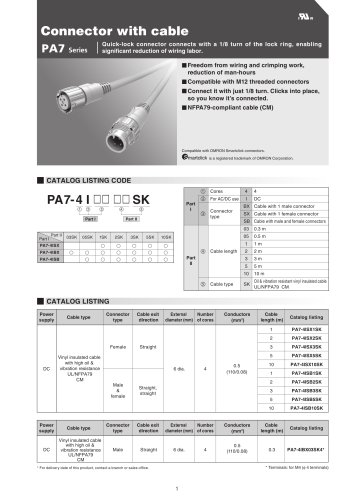
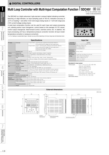
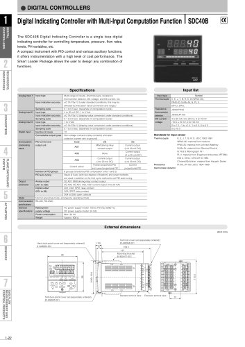
Distributed Multi-Channel Controller The DigitroniK DMC10 is a module type 2 or 4-channel compact digital controller. Inputs are full multiple, supporting thermocouple, RTD, DC voltage and DC current inputs. Control mode is time proportional (ON/OFF) PID control. Control outputs are relay output and voltage pulse output. Continuous PID control is attained by an auxiliary output, A dedicated PC loader configures setup, control parameters • Full multiple input function is equipped, supporting vari- ous analog input sensors. • Communication function (RS-485) is provided as stan- dard. Communication performance is enhanced by sup- • Two event outputs are available for each channel. "AND/ OR" logic is used as an event between channels by the internal event function. (Under development) • Current transformer (CT) input is provided for each chan- Easy setting by a personal computer loader, also enabling monitoring of trial operation. Connector type and terminal type models available for the A side-face connector is used to connect modules, there- fore communication and power wiring is not required. "Quick-FITTER" Control, a high-speed recovery control function is equipped as standard. This function enables the quick recovery of setpoint temperature and over-shoot suppression at the occurrence of disturbances. DMC10 Basic Function Block Diagram Process variable (PV) inputs Heater burnout • Decimal point location • Data transmission/ External switch input (2 points for each channel) •RUN/READY • Timer start • SP group • DO latch cancellation • AUTO/MANUAL • Direct/reverse action Heater current input Control operation Self tuning Control output • Output limiter • Changing rate upper-lower limit • Deviation upper/ lower/upper-lower limit - Differential between Upper/lower/upper-lower limit Self Tuning Loop diagnostics Heater burn-out Actuator short-circuit Communication input/ouput (COMM) Auxiliary output ■ Deviation between channels
Open the catalog to page 1
Table 1 Input type and ranges Event Output Module Specifications • The number of event outputs can be added in combination with the DMC10. • One event module can be connected to a side-connection gang-mounted group. • By adding an event output module, this unit can respond to a wide variety of tem- perature control application requirements.
Open the catalog to page 4
■ Model Selection Guide ■ Peripheral Device Model Numbers • Event Output Module [T] [T] \W\ Qv] [V] [vj] [W] Example: DMC10E4CR0000 • PC loader software [T] QD Example: SLP-D10J20 "PC/AT converter complies with Windows 95/98
Open the catalog to page 5
I Wiring Common for both 2CH/4CH models CT input (CH1) Thermocouple input RTD input (CH3) (CH3) 21 21 A 21 CT 22 Event output (CH1/2) Event 1 Event 2 23 24 22 22 B 23 23 C Relay output (CH3) 24 (CH1/2) RSW2 25 23 24 25 25 26 CT 27 Event output (CH3/4) Event 3 Event 4 28 29 External contact input 30 27 B 28 28 C Relay output (CH4) 29 28 29 30 30 12 Thermocouple input RTD input (CH1) (CH1) 13 13 C 23 14 14 B 15 A Relay output (CH2) 16 DC voltage DC current input (CH4) 26 V 19 19 B 20 30 13 V 14 mA 15 17 Thermocouple input RTD input (CH2) (CH2) 18 18 C 28 DC voltage DC current input (CH1)...
Open the catalog to page 7
■ Dimensions for Mounting with Screws ■ Name of Each Unit and Function Loader jack- : Used to set/monitor by DMC10 PC loader, Connected using the dedicated cable provided with the loader. Communication address- ress setting at the host POWER lamp : Lights when power is applied Flashing continues for approx. after power is supplied. separation switch - Power supply terminal This device can be connected to other modules, using con- nectors provided on both the left and right sides. Be sure to connect the module before mounting on DIN rail or by screws. Power and CPL communications are jointly...
Open the catalog to page 8
Mount the instrument at a location that satisfies the fol- lowing conditions: • Mount the instrument in location: Not subject to high or low temperatures, or high or low humidity. • Free of corrosive gas (sulfide gas, etc.) • Free of dust particles, soot, or the like. • Not exposed to direct sunlight, rain or wind • Free of mechanical vibrations and shock • Do not mount the instrument near a high-voltage line, a welder, or electrical noise generating sources • Make sure the instrument is within 15m from a boiler or other high-voltage ignition devices. • The location should not be subject to...
Open the catalog to page 9
This product has been designed, developed and manufactured for general-purpose application in machinery and equipment. Accordingly, when used in the applications outlined below, special care should be taken to implement a fail-safe and/or redundant design concept as well as a periodic maintenance program. • Safety devices for plant worker protection • Start/stop control devices for transportation and material handling machines • Aeronautical/aerospace machines • Control devices for nuclear reactors Never use this product in applications where human safety may be put at risk. Specifications...
Open the catalog to page 12All Azbil North America catalogs and technical brochures
-
 NX-D25
2 Pages
-
 NX-CB2
1 Pages
-
 NX-CL1/CL2/TL1/TR1
1 Pages
-
 RN748A
1 Pages
-
 HM
HM1 Pages
-
 ECM3000 Control Motor
8 Pages
-
 Multi-Loop Controller SDC46A
2 Pages
-
 Single Loop Controller SDC25
2 Pages
-
 Single Loop Controller SDC15
2 Pages
-
 YYU4 Simple Thermocouple
1 Pages
-
 Fiber Units HPF Series
26 Pages
-
 FL2 Series
6 Pages
-
 LJM-D series
4 Pages
-
 BZ Series Basic Switch
9 Pages
-
 CMG Series Gas Flow Monitor
4 Pages
-
 MCF Series Air Flow Meter
2 Pages
-
 MAGNEW Series
3 Pages
-
 HP100
HP10010 Pages
-
 HPX
HPX10 Pages
-
 HPX-AG
20 Pages
-
 APT
APT2 Pages
-
 APM
APM6 Pages
-
 FL7M
FL7M10 Pages
-
 ATT70
ATT708 Pages
-
 WaterMAG
8 Pages


Archived catalogs
-
 MagneW 3000 Plus CA2-MGG-01
4 Pages
-
 MagneW 3000 PLUS HENRI
2 Pages
-
 MagneW Two-Wire Plus
20 Pages

