Catalog excerpts

CV3000 Series Control Valve Model : HLS,HTS,HPS,HLC,HSC,HAV User's Manual Azbil Corporation
Open the catalog to page 1
NOTICE While this information is presented in good faith and believed to be accurate,Azbil Corporation disclaims the implied warranties of merchantability andfitness for a particular purpose and makes no express warranties except asmay be stated in its written agreement with and for its customer. In no event is Azbil Corporation liable to anyone for any indirect, special orconsequential damages. The information and specifications in this documentare subject to change without notice. © 2012 - 2014 Azbil Corporation All Rights Reserved.
Open the catalog to page 2
Table of Contents Chapter 1. General . . . . . . . . . . . . . . . . . . . . . . . . . . . . . . . . . . . . . . . . . . . . . . . . . . . . . . . . . . . . . . . . 1 1-1. Scope . . . . . . . . . . . . . . . . . . . . . . . . . . . . . . . . . . . . . . . . . . . . . . . . . . . . . . . . . . . . . . . . . . . . . . . . . . . . 1 1-2. Main components of control valves . . . . . . . . . . . . . . . . . . . . . . . . . . . . . . . . . . . . . . . . . . . . . . . . . . 1 1-3. Structures . . . . . . . . . . . . . . . . . . . . . . . . . . . . . . . . . . . . . . . . . . . . . . . . . . . . . ....
Open the catalog to page 3
Chapter 9. nstructlons for Bellows Sealed Type of Control Valves . . . . . . . . . . . . . . . . . . 68 I 9-1. Model HLS control valves . . . . . . . . . . . . . . . . . . . . . . . . . . . . . . . . . . . . . . . . . . . . . . . . . . . . . . . . . . 68 9-1-1. Structures . . . . . . . . . . . . . . . . . . . . . . . . . . . . . . . . . . . . . . . . . . . . . . . . . . . . . . . . . . . . . . . . . 68 9-1-2. Disassembly and assembly . . . . . . . . . . . . . . . . . . . . . . . . . . . . . . . . . . . . . . . . . . . . . . . . . . . 70 9-2. Model HTS control valves . . . . . . . . . . . ....
Open the catalog to page 4
Chapter 1. General 1-1. Scope This manual covers the instructions for the following Control Valves. ■ Model HLS : Small-port single-seated control valves ■ Model HLC : Small-port cage guide type single-single seated control valves ■ Model HTS : Top-guide single-seated control valve ■ Model HSC : Cage type single-seated control valve ■ Model HPS : Top-guide high-pressure single-seated control valves ■ Model HAV : Venturi throat type angle control valves. For the valve positioners, refer the following operators manuals. ■ Model VPE OM2-8310-0410 Pneumatic valve positioner for small...
Open the catalog to page 5
Figure 1-1A Small-Port Single Seated Control Valve, Model HLS (Direct Action Type) Figure 1-2A Top-Guided Single Seated Control Valve, Model HTS Figure 1-3A Top-Guided High-Pressure Single Seated Control Valve, Model HPS Figure 1-3B Venturi-Throat-Type Angle Control Valve, Model HAV
Open the catalog to page 6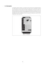
1-4. Nameplate A nameplate as shown in Figure 1-4 is posted on each control valve. The nameplate indicates the model number, valve size, pressure rating, trim material, date of manu.facture and other major specifications of the control valve. Before installing the con.trol valve, make sure that the specifications indicated on the nameplate conform with the conditions of use. The nameplate indicate also the product number (PROD.NO.) of the control valve. Please mention this number also when consulting an Azbil Corp. agent for replacement of parts or other modification of the control valve.
Open the catalog to page 7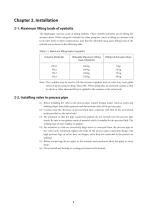
Chapter 2. Installation 2-1. Maximum lifting loads of eyebolts The diaphragm case has a pair of lifting eyebolts. These eyebolts primarily are for lifting the actuator alone. When using the eyebolts for other purposes (such as lifting an actuator bed to its valve body or other components), note that the allowable maxi.mum lifting loads of the eyebolts are as shown in the following table. Table 2-1 Maximum lifting loads of eyebolts Note: The eyebolts may be used to lift the actuator together with its valve buy (cast globe valve) of up to pressure rating “Class 600”. When doing this, be...
Open the catalog to page 8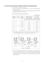
(1) Check that there is no leak from air piping. (2) Check that the bolts and nuts of the diaphragm case are not loose. Standard tight.ening torques are as follows: (3) Tighten the packing flange nuts to prevent leak from the gland packing chapter. Standard tightening torques are as shown in Table 2-2. Table 2-2 Tightening Torques of Packing Flange Nuts Note: The tightening torques mentioned in the above are only to give you reference values. Note that tightening torques may vary depending on the type of packing. PTFE Yarn Packing Graphite + Graphite Yarn V PTFE + PTFE Yarn Packing...
Open the catalog to page 9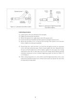
Squeeze Screw Lubricator Handwheel Figure 2-3 Lubricator for High Pressure Valve (Class 600 or higher) Figure 2-2 Lubricator (Class 600 or under) Lubricating procedure (a) prepare grease of the type indicated on the nameplate. (b) Tightly close the lubricator handwheel. (c) Remove the squeeze screw, apply grease, and set the squeeze screw. (d) Loosen the lubricator handwheel and drive grease by turning the squeeze screw. (e) Repeat the procedure of 0), (c) and (d) until turning of the squeeze screw becomes heavier. Tightly close lubricator handwheel. (5) Pressurizing valve, check that there...
Open the catalog to page 10
Chapter 3. Inspection and Maintenance Inspect and service the actuator as follows: (1) Tightening the gland: Tighten the gland once in every 6 months or thereabout. The tightening procedure is as given in Section 2-3-(3). Lubricating the gland: (2) Lubricating the gland once in every 6 months or thereabout. The lubricating procedure is as given in Section 2-3-(4). (3) Check for hunting of valve Position: Refer to Chapter 10 ''Troubleshooting.'' (4) Check for abnormal noise and vibration: Refer to Chapter 10 ''Troubleshooting.''
Open the catalog to page 11
Chapter 4. Disassembly and Assembly This Chapter covers the disassembly and assembly procedures of the actuator for its overhaul or modification. 4-1. Detaching actuator from valve body See Figure 4-7. (1) Apply to the actuator an air pressure so that the valve position pointer is at a point of 10% - 20% above the fully closed point. (2) Loosen the clamping-bolts of the stem connector, remove the stem connector, and detach the actuator stem from the valve stem. (3) Remove the clamping-nut of the yoke. (4) Raise the actuator to detach it from the valve body. Precautions: or detaching the...
Open the catalog to page 12All Azbil North America catalogs and technical brochures
-
NX-D25
2 Pages
-
NX-CB2
1 Pages
-
NX-CL1/CL2/TL1/TR1
1 Pages
-
RN748A
1 Pages
-
HM
1 Pages
-
ECM3000 Control Motor
8 Pages
-
Multi-Loop Controller SDC46A
2 Pages
-
Single Loop Controller SDC25
2 Pages
-
Single Loop Controller SDC15
2 Pages
-
YYU4 Simple Thermocouple
1 Pages
-
Fiber Units HPF Series
26 Pages
-
FL2 Series
6 Pages
-
LJM-D series
4 Pages
-
BZ Series Basic Switch
9 Pages
-
CMG Series Gas Flow Monitor
4 Pages
-
MCF Series Air Flow Meter
2 Pages
-
MAGNEW Series
3 Pages
-
HP100
10 Pages
-
HPX
10 Pages
-
HPX-AG
20 Pages
-
APT
2 Pages
-
APM
6 Pages
-
FL7M
10 Pages
-
ATT70
8 Pages
-
WaterMAG
8 Pages
Archived catalogs
-
MagneW 3000 Plus CA2-MGG-01
4 Pages
-
MagneW 3000 PLUS HENRI
2 Pages
-
MagneW Two-Wire Plus
20 Pages


