
Catalog excerpts

NOTICE While the information in this manual is presented in good faith and believed to be accurate, Azbil Corporation disclaims any implied warranty of merchantability or fitness for a particular purpose and makes no express warranty except as may be stated in its written agreement with and for its customer. In no event shall Azbil Corporation be liable to anyone for any indirect, special or consequential damages. This information and specifications in this document are subject to change without notice. © 2014 Azbil Corporation All Rights Reserved.
Open the catalog to page 2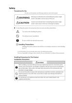
Precautions for Use For safe use of the product, the following symbols are used in this manual. WARNING CAUTION Warnings are indicated when mishandling the product might result in the death or serious injury of the user. Cautions are indicated when mishandling the product might result in minor injury to the user or damage to property. ■■ In describing the product, this manual uses the icons and conventions listed below. Use caution when handling the product. The indicated action is prohibited. Be sure to follow the indicated instructions. Handling Precautions: Handling Precautions indicate...
Open the catalog to page 3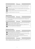
CAUTION ©When wiring, check the specifications carefully and make sure to wire correctly. Incorrect wiring can cause device damage or malfunction. ©Supply electric power correctly according to the specifications. Supplying power that differs from the specifications can damage the device. Use a DC power supply that has overload protection. ©When removing this device for maintenance, be careful of residual pressure or residual process gas. Leakage of process gas is dangerous. ©When working on the vent, check its direction so that people do not come into contact with vented gas. There is a...
Open the catalog to page 4
Table of Contents Chapter 1. Important document information . . . . . . . . . . . . . . . . . . . . . . . . . . . . . . . . . . . . . . . 1 1-1. About this document. . . . . . . . . . . . . . . . . . . . . . . . . . . . . . . . . . . . . . . . . . . . . . . . . . . . . . . . . . . . . . . . . . . . 1 1-1-1. Document function. . . . . . . . . . . . . . . . . . . . . . . . . . . . . . . . . . . . . . . . . . . . . . . . . . . . . . . . . . . . . . . 1 1-1-2. Additional standard documentation on the device . . . . . . . . . . . . . . . . . . . . . . . . . . . . . . . . 1 1-1-3. Safety...
Open the catalog to page 5
6-3-1. Display elements. . . . . . . . . . . . . . . . . . . . . . . . . . . . . . . . . . . . . . . . . . . . . . . . . . . . . . . . . . . . . . . . 17 6-3-2. Local operation. . . . . . . . . . . . . . . . . . . . . . . . . . . . . . . . . . . . . . . . . . . . . . . . . . . . . . . . . . . . . . . . . . 19 Chapter 7. Integrating the transmitter via HART® protocol. . . . . . . . . . . . . . . . . . . . . . . . . . 20 7-1. HART device variables and measured values . . . . . . . . . . . . . . . . . . . . . . . . . . . . . . . . . . . . . . . . . . . . 20 7-2. Device variables and measured...
Open the catalog to page 6
1-1-3. Safety Instructions When using in hazardous areas, the national safety requirements must be met. Separate Ex documentation is contained in these Operating Instructions for measurement systems that are to mounted in hazardous areas. Strict compliance with the installation instructions, ratings and safety instructions as listed in this supplementary documentation is mandatory. Ensure you are using the correct Ex documentation for the relevant Ex-approved device. The number of the related Ex documentation is indicated on the nameplate. You can use this Ex documentation if the two...
Open the catalog to page 7
Chapter 2. Basic safety instructions 2-1. Requirements for the personnel The personnel for installation, commissioning, diagnostics and maintenance must fulfill the following requirements: ► Trained, qualified specialists must have a relevant qualification for this specific function and task ► Are authorized by the plant owner/operator ► Are familiar with federal/national regulations ► Before beginning work, the specialist staff must have read and understood the instructions in the Operating Instructions and supplementary documentation as well as in the certificates (depending on the...
Open the catalog to page 8
Chapter 3. Identification 3-1. Device designation The following options are available for identification of the device: Nameplate specifications 3-1-1. Nameplate The right device? Compare and check the data on the nameplate of the device against the requirements of the measuring point: 3 Input: 11-42V Current consum.: 23,6 mA Ext. ord. cd.: XXXXXXXXXXXXX# Ser.no.: 012345678910 Dev.Rev: 1 xx.yy.zz FW: Made in Germany 2011 D-87484 Nesselwang Fig 3-1. Nameplate of the head transmitter (example, Ex version) 1 Power supply, current consumption and extended order code 2 Serial number, device...
Open the catalog to page 9
3-3-1. CE mark, Declaration of Conformity The device therefore meets the legal requirements of the EC guidelines. The manufacturer confirms that the device is compliant with the relevant guidelines by applying the CE mark. 3-3-2. HART® protocol certification The temperature transmitter is registered by HART® Communication. The device meets the requirements of the HART Communication Protocol Specifications, Revision 7.0. 3-3-3. Functional safety The device is optionally available for use in safety systems as per IEC 61508. ■ SIL 2: Hardware version ■ SIL 3: Software version 3-3-4. Registered...
Open the catalog to page 10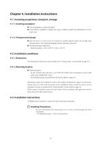
Chapter 4. Installation instructions 4-1. Incoming acceptance, transport, storage 4-1-1. Incoming acceptance ■ Is the packaging or content damaged? ■ Is the delivery complete? Compare the scope of delivery against the information on your order form. 4-1-2. Transport and storage ■ Pack the device in such a way as to protect it reliably against impact for storage (and transportation). The original packaging provides optimum protection. ■ Permitted storage temperature: - Head transmitter: -50 to +100 °C (-58 to +212 °F) 4-2. Installation conditions 4-2-1. Dimensions The dimensions of the...
Open the catalog to page 11
Procedure for mounting in a field housing, pos. B: 1. Open the cover (1) of the field housing (4). 2. Guide the mounting screws (2) through the lateral bores of the head transmitter (3). 3. Screw the head transmitter to the field housing. 4. After wiring, close the field housing cover (1) again. (Refer to page 8)
Open the catalog to page 12All Azbil North America catalogs and technical brochures
-
 NX-D25
2 Pages
-
 NX-CB2
1 Pages
-
 NX-CL1/CL2/TL1/TR1
1 Pages
-
 RN748A
1 Pages
-
 HM
HM1 Pages
-
 ECM3000 Control Motor
8 Pages
-
 Multi-Loop Controller SDC46A
2 Pages
-
 Single Loop Controller SDC25
2 Pages
-
 Single Loop Controller SDC15
2 Pages
-
 YYU4 Simple Thermocouple
1 Pages
-
 Fiber Units HPF Series
26 Pages
-
 FL2 Series
6 Pages
-
 LJM-D series
4 Pages
-
 BZ Series Basic Switch
9 Pages
-
 CMG Series Gas Flow Monitor
4 Pages
-
 MCF Series Air Flow Meter
2 Pages
-
 MAGNEW Series
3 Pages
-
 HP100
HP10010 Pages
-
 HPX
HPX10 Pages
-
 HPX-AG
20 Pages
-
 APT
APT2 Pages
-
 APM
APM6 Pages
-
 FL7M
FL7M10 Pages
-
 ATT70
ATT708 Pages
-
 WaterMAG
8 Pages


Archived catalogs
-
 MagneW 3000 Plus CA2-MGG-01
4 Pages
-
 MagneW 3000 PLUS HENRI
2 Pages
-
 MagneW Two-Wire Plus
20 Pages

