 Website:
Azbil Europe NV
Group: azbil
Catalog excerpts

• Designed for general industrial use, not for safety equipment. • Do not connect this device to AC power. Doing so might cause rupture or burnout. Countermeasures to improve detection reliability: ► Cautions for use • Use the included mounting screws for installation. The recommended tightening torque is 1.6 to 2.1 Nm If screws other than the included ones are used, be sure that they extend into this product at least 5 mm. Also, note that the use of stainless steel screws with this product can lead to corrosion. • Note that if this product is exposed to a corrosive environment such as salt water (but not cutting oil), galvanic corrosion may result. • Although the cable is oil-resistant, watch for hardening of the cable outer sheath or loss of seal that can be caused by some kinds of oil (such as non-watersoluble cutting oil or machine oil). Also, do not allow water or oil to be splashed on the end of the cable. • The lens cover is made of glass and can be damaged by a direct shock. Do not use this product in an application where broken glass might create a dangerous state. • Do not connect this switch to AC power. Doing so might cause rupture or burnout. • Approx. 60 ms is necessary after power on to reach stable operation. • Place a switch in the case to avoid sunlight or rain when used in outdoors. • Avoid usage with big vibration or shock which may cause misalignment of light axis. • To avoid malfunction, install a shielding plate, etc., so that the lens is not exposed to water or oil. •Do not use in an atmosphere with chemicals (organic, acid, alkali). •Confirm the stable operation by shielding or changing mounting direction if ambient light is very strong. • Keep dust away from lens by using sealed case and air purge. • Put the protective cover on the switch if it is likely to be struck by an object or person. • Do not bend the part of the cable nearest to the switch with minimum radius of 30 mm and also avoid continuous bending stress. • Cable cut may occur when cable is pulled with over 50 N. • Please wipe the reflector with soft cloth (dry or with a little water). Do not use a organic solvent such as alcohol, benzine, acetone or thinner. • Be careful of mutual interference when several switches are applied in close proximity. Handle the switch with care. • If a retroreflective-scan is used to detect highly reflective objects or objects that disturb polarization, unreliable detection may result. In such a case, take the following countermeasures: Examples of target objects that might cause faulty operation: • Objects covered with transparent film • Translucent objects (such as a semitransparent case) • Mirrors or highly reflective mirrorlike objects • Mount the switch at an angle to the target object. • Increase the distance between the switch and the target object. • It can be expected that cables will become stiff at low temperatures (below 0 °C). In such a case, avoid bending cables or subjecting them to vibration or impact. • Note that the operation button will become stiff at low temperatures (below 0 °C). Photoelectric Switches for Harsh Environments B^MBS Models H2B-T_/H2B-P_/H2B-A_ ► Wiring cautions • If an extension of cable is necessary, use a 0.3 mm2 minimum cable of 100 m maximum length. • Route the cables of the switch separately from power lines or through an exclusive conduit, otherwise the electrical noise or surge may cause incorrect operation or damage. • When using a commercially available switching regulator, ground the FG (frame ground) and G (ground) terminals. Otherwise the switching noise may cause incorrect operation. • When using a load which generates a transient current, connect a current limiting resistor between the load and the output terminal. Otherwise the short-circuit protection may function. ■ Thru-scan model and retroreflective model 1. Move the emitter and receiver (Main body and reflector in case of a retroreflective model) up, down, right, and left, and then align them in the center of the area where the green stable-operation indicator lights up. ■ Diffuse-scan model 1. Mount the photoelectric switch pointing toward the desired detection position. 2. Check switch operation using a target object then use the Auto Adjust button to adjust the sensitivity setting. Please read “Terms and Conditions” from the following URL before ordering and use. https://www.azbil.com/products/factory/order.html ^!_/ Other product names, model numbers and company names may be trademarks of the respective company. [Notice] Specifications are subject to change without notice. No part of this publication may be reproduced or duplicated without the prior written permission of Azbil Corporation. Rugged photoelectric switches Azbil Corporation Advanced Automation Company Yamatake Corporation changed its name to Azbil Corporation on April 1, 2012. 1-12-2 Kawana, Fujisawa Kanagawa 251-8522 Japan URL: https://www.azbil.com 1st Edition : Oct. 2019-SK
Open the catalog to page 1
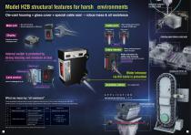
Die-cast housing + glass cover + special cable seal ^ robus tness & oil resistance Polyether sulfone + multilayer seal These photoelectric switches pass in-house oil resistance tests that use (1) the oil used in testing for the JEM IP67g standard and (2-7) six types of water-soluble cutting oil that are widely used in manufacturing processes (see table below). Note: Test results are for reference only. Please verify with the actual products. Detecting engine blocks or metal parts Cable port Before press fitting <■! High sealing performance by press-fit NBR seal After press fitting Water...
Open the catalog to page 2
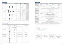
Specifications Detection method Detection range Light source Wiring method Built-in horizontal slit Adjustable sensitivity Reflectors and Brackets Detection method *1. A FET is used for output. *2. In combination with reflector FE-RR8. *3. Mounting the emitter or receiver on an angle affects the ability to detect objects. *4. In a low-temperature environment, the cable will become stiff. Do not bend it forcefully or exert excessive force on it while at a low temperature because it may crack. ■ Thru-scan emitter Power indicator Main circuit JL Blue ■ Thru-scan receivers, retroreflective...
Open the catalog to page 3All Azbil Europe NV catalogs and technical brochures
-
V8C/V8S
4 Pages
-
F4Q
6 Pages
-
F7M
4 Pages
-
Air purge control
2 Pages
-
Liquid temperature control
2 Pages
-
Wafer detection sensor
2 Pages
-
Wafer alignment sensor
2 Pages
-
Liquid level sensors
2 Pages
-
Liquid leakage sensors
2 Pages
-
Paperless Recorder ARF
7 Pages
-
Fiber Unit Selection Guide HPF
26 Pages
-
Gas Mass Flowmeter CMS
4 Pages
-
Air Flow Meter MCF
8 Pages
-
WET process sensors
16 Pages
-
AT9000
2 Pages
-
Digital Mass Flow Controller
6 Pages
-
High-Accuracy Position Sensors
16 Pages
-
HP series
16 Pages
-
Capacitance Diaphragm Gauge
4 Pages
-
Meets Global Standards
12 Pages
-
AX Series Vortex Meters
12 Pages
-
GasCVD
2 Pages
-
MagneW 3000 PLUS+
2 Pages
-
MagneW NeoPLUS
2 Pages
-
Single Loop Controller SDC15
2 Pages
-
Azbil Group introduction
8 Pages


