
- Catalogs
- Azbil Europe NV
- Adjustable Proximity Sensor H3C


Adjustable Proximity Sensor H3C

Adjustable Proximity Sensor H3C
Catalog excerpts

Connector cables azbil Fastening the connector Align the grooves and rotate the nut on the connector cable side by hand until it fits tightly with the switch-side connector. Adjustable Proxi mity SensorModel H3C-H When connecting a pre-leaded quick-lock connector-type sensor, be sure to use a model PA5-___connector cable. Precautions for Use • Mutual interference prevention If proximity sensors are installed side-by-side or facing each other, mutual interference will occur, resulting in malfunction. Maintain the minimum distances between sensors according to the table below. • Tightening torque Use the supplied nuts and toothed washers for installation. The maximum tightening torque of the nuts varies depending on the distance from the sensor head. The maximum tightening torque is indicated in the table below. When tightening, do not hold or turn the indicator (plastic part). The maximum tightening torque can vary depending on the materials and surface conditions of the mounting plates, mounting housings, nuts, washers, and other parts used for the sensor. Check in advance that the torque is appropriate for the actual combination of parts used. A: Distance from the proximity sensor’ s sensing surface to an iron plate in front of the sensor B: Distance from the proximity sensor’ s axis to an iron plate in front of the sensor Please read “Terms and Conditions” from the following URL before ordering and use. https://www.azbil.com/products/factory/order.html Other product names, model numbers and company names may be trademarks of the respective company. Azbil Corporation Advanced Automation Company 1-12-2 Kawana, Fujisawa Kanagawa 251-8522 Japan URL: https://www.azbil.com [Notice] Specifications are subject to change without notice. No part of this publication may be reproduced or duplicated without the prior written permission of Azbil Corporation. Using a teaching method, the threshold level at the desired sensing position can be set easily. 1st Edition : Mar. 2020-SO Azbil Corporation
Open the catalog to page 1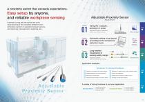
A proximity switch that exceeds expectations. Easy setup by anyone, and reliable workpiece sensing Automatic tuning sets the optimal set point using teaching of the workpiece detection level, eliminating variation in operation between sensors, and improving the equipment’s operating rate. Adjustable Proximity Sensor Model H3C-H_ Using the 2 outputs, sensing in 4 areas Eliminates the need for troublesome positioning of multiple switches. [ Zone sensing ] Automatic setting of set points according to the workpieces’ detection levels ON/OFF setting is available within the sensing area. Long-awaited...
Open the catalog to page 2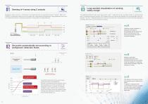
Sensing of 4 areas using 2 outputs Feature Long-awaited visualization of sensing safety margin [ Visualization ] Sensing of 4 areas is done by a combination of the operational logic and operational modes of outputs 1 (BDC1) and 2 (BDC2). A single switch does the work of multiple units, saving space and significantly cutting adjustment man-hours. This reduces the need for troublesome adjustment of the position of multiple switches. The dedicated setting tool helps check the proximity switch’ s positional accuracy and safety margin for sensing (excess gain). Conventional proximity switches’ LED...
Open the catalog to page 3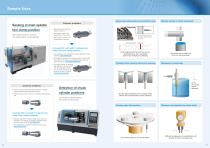
Sample Uses Sensing of main spindle tool clamp position With multiple proximity switches, tool clamp position can be detected. Common problems Sensor failure detection with two inverted ON/OFF outputs ● Adjusting switch positions takes a long time. ● Adjustment results vary depending on the worker. Ex.: A proximity sensor in a high location cannot be seen. ● After setup, the amount of excess gain is unknown. Normal operation A single H3C unit (with 2 outputs) can detect the tool clamp position. ● It is necessary only to adjust the setting distances of the switches. Less adjustment work ● The...
Open the catalog to page 4
Standard mode This function sets the set point (threshold level) of output 1 (BDC1) or output 2 (BDC2) as well as the operational mode. [ Single Value Teach ] Sets the set point (threshold level) to the value obtained by multiplying the teach point and the setting ratio (10 to 200%). [ Two Value Teach ] Sets the set point to the midpoint of the two teach points. [ Dynamic Teach ] Sets the set point to the midpoint of the maximum and the minimum sensing levels of a moving workpiece in the interval from teach start to teach stop. [ Single Value Teach ] Sets ON and OFF at two teach points. [ Single...
Open the catalog to page 5
Output indicator Diagram of the output circuit and wiring ■ Single point mode SIO (standard I/O) ■ Single point mode lO-Link communication Note: • The C/Q output and the orange indicator turn on according to set point 1, set point 2, and the N.O./N.C. setting for BDC1. • The DO output and the green indicator turn on according to set point 1, set point 2, and the N.O./N.C. setting for BDC2. DC 10-30V NC ON ON ■ IO-Link communication mode (COM mode) External dimensions Indicator lamp: green Lit (cycle: 1 s) Note: • Detection is carried out according to set point 1, set point 2, and the N.O./N.C....
Open the catalog to page 6Archived catalogs
 Azbil Group introduction
8 Pages
 MagneW NeoPLUS
2 Pages
 MagneW 3000 PLUS+
2 Pages
 GasCVD
2 Pages
 AX Series Vortex Meters
12 Pages
 Meets Global Standards
12 Pages
 Capacitance Diaphragm Gauge
4 Pages
 High-Accuracy Position Sensors
16 Pages
 Digital Mass Flow Controller
6 Pages
 AT9000
2 Pages
 WET process sensors
16 Pages
 Gas Mass Flowmeter CMS
4 Pages
 Fiber Unit Selection Guide HPF
26 Pages
 Paperless Recorder ARF
7 Pages
 Liquid leakage sensors
2 Pages
 Liquid level sensors
2 Pages
 Wafer alignment sensor
2 Pages
 Wafer detection sensor
2 Pages
 Liquid temperature control
2 Pages
 Air purge control
2 Pages
 F7M
F7M4 Pages
 F4Q
F4Q6 Pages
 V8C/V8S
4 Pages


- Valve
- Control valve
- Flowmeter
- Pneumatic valve
- Volume flow monitor
- Liquid flow monitor
- Pressure transmitter
- Level limit switch
- Analog pressure transmitter
- Liquid level detector
- Pneumatically-operated valve
- Waterproof flow meter
- Gas flow monitor
- Digital temperature control
- Stainless steel flow monitor
- Lift valve
- Cylindrical proximity sensor
- Industrial flow monitor
- Pressure probe