Catalog excerpts

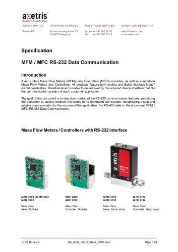
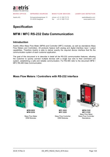
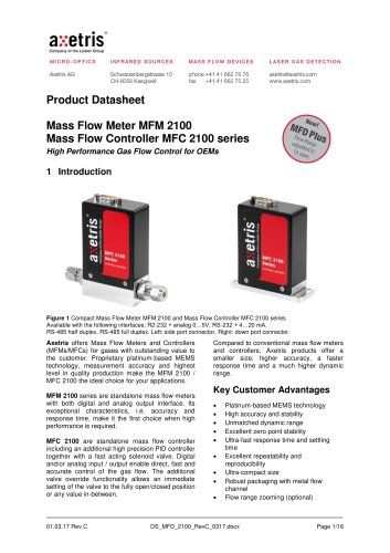
LASER GAS DETECTION axetris@axetris.com www.axetris.com _ • ® axetris Company of the Leister Group MICRO-OPTICS INFRARED SOURCES Introduction Axetris offers Mass Flow Meters (MFMs) and Controllers (MFCs) modules, as well as standalone Mass Flow Meters and Controllers. All products feature both analog and digital interface input / output capabilities. Therefore Axetris is able to deliver exactly the required device interface that fits the communication system of each customer application. The goal of this document is to describe in detail all the RS-232 communication features, permitting the customer to quickly connect the device to its command unit system, establishing a safe and reliable communication for the success of the application. For RS-485 refer to the document MFM / MFC RS-485 Data Communication. Mass Flow Meters / Controllers with RS-232 interface MFC 2122 MFC 2132 Mass Flow Controller Stand alone
Open the catalog to page 1
Table of contents 1 General Description 3 3 Pin assignment for stand alone types 7 6 Commands & variables list definition 15 7 Coding - decoding digital data 17 11 Important Notice / Disclaimer 24
Open the catalog to page 2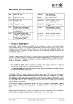
Abbreviations, terms and definitions 1 General Description Axetris MFM / MFC modules are capable to communicate by means of analog and digital communication interfaces. For the standalone MFM / MFC modules the analog input / output is either of voltage type or current type. For the modules, only the voltage type is available. The way the customer chooses to communicate with the device, the set point and the gas flow can be set subsequently at any time. The serial interface protocol is based on a master slave communication between the device and typically a computer. To response to the...
Open the catalog to page 3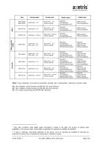
Table 1 Type comparison and product functionality including main communication features in customer mode. MFx 20xx: Modules without housing and RS-232 TTL level Interface MFx 22xx: Modules without housing and RS-232 EIA level Interface MFx 21xx Types with housing and RS-232 BA Interface Only main customer mode digital output information is listed in this table. For access to internal data availability in the service mode, see chapter 5 regarding the requests & variables list definition. 2 In case of multi-gas, multi-range calibration of the device. Up to 8 channels are available (2 channels...
Open the catalog to page 4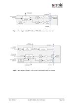
Gas flow meter (Analog/Digital) Gas flow Out Data & command (Digital I/O) EEPROM Parameters Calibration Data Sensor Chip Heater regulation Figure 1 Block diagram of the MFM 2100 and MFM 2200 series of mass flow meter PID_out (Analog/Digital) Set point (Analog/Digital) Valve override (Analog/Digital) Data & command (Digital I/O) uP T Compensation Linearization EEPROM Parameters Calibration Data Valve Driver Sensor Chip Gas flow meter (Analog/Digital) Heater regulation Figure 2 Block diagram of the MFC 2100 and MFC 2200 series of mass flow controller
Open the catalog to page 5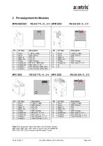
Table 2 Pin assignment Mass Flow Meter and Controller modules MFM 2020, MFM 2021, MFC 2022 connector type JST-SM09B-SR MFM 2222, MFC 2222 connector type Micromatch 8-pole
Open the catalog to page 6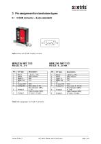
- • ® axetris Company of the Leister Group 3 Pin assignment for stand alone types 3.1 D-SUB connector - 9 pins (standard) Table 3 Pin assignment for D-SUB 9 connector
Open the catalog to page 7
Device input / output configuration There is no default configuration setup. Due to the many possibilities that are available, the devices are delivered with the features which correspond to the customer requirements. Analog input / output is either from voltage type or current type. The digital input / output is RS232. RS485 is also available (RS-485 Half Duplex MFM 2x40, MFC 2x42 ; RS-485 Full Duplex MFM 2x50, MFC 2x52, see document “MFM / MFC RS-485 Data Communication”). The type of the analog input / output, voltage or current, is set by the manufacturer at the factory level. The way...
Open the catalog to page 8
Valve override state Selected input mode for the set point (analog or digital) Write Data: - Set point - Valve override - Input mode for the set point (analog or digital) In service mode, much more digital data is accessible to allow the customer to adapt the device to his own needs, i.e. device trimming, filter parameters, or even customer calibration for channels 3 to 8 (1 and 2 are accessible only by the manufacturer and are factory calibrated), thus allowing to fully adapt the device to particular customer requirements. See chapter 5, list of requests and variables, for more information...
Open the catalog to page 9
The MFC 2022 and MFC 2222 are small compact gas flow controller modules including an advanced internal PID controller with a fast acting solenoid valve. Its main purpose is to be integrated into an OEM system. According to the needs of the customer, the data output can be read in analog (voltage or digital modes using RS-232 TTL (MFC 2022) or RS-232 EIA (MFC 2222). Analog voltage input / output is selected as default input when not specified otherwise during ordering. The preferred way to communicate with the device, analog or digital, can be set later at any time with the corresponding...
Open the catalog to page 10
The MFM 2120 is a standalone meter. Its purpose is to be a ready-to-use gas flow meter with standard gas fittings. According to the needs of the customer, the data output can be read in analog (voltage or current) or digital using RS-232 (EIA 232) with direct connection to the PC. Analog voltage or analog current input / output is selected as default at the factory level when ordering. The way the customer wants to communicate with the device, analog or digital, can be set later at any time with the corresponding digital command. This configuration is stored in EEPROM making the device...
Open the catalog to page 11
- Offset value - Gas type that is currently measured (in case of multi-range and/or multi-gas calibration device). Up to 8 ranges for one device can be calibrated. - Calibrated gas information (gas type, full scale range, calibration conditions, see chapter 6 for more details) - Set point - PID_out - Valve override state - Selected input mode for the set point (analog or digital) Write Data: - Channel selection (in case of multi-range and/or multi-gas calibration) - Offset zeroing - Set point - Valve override - Input mode for the set point (analog or digital) In service mode, even more...
Open the catalog to page 12All Axetris AG catalogs and technical brochures
-
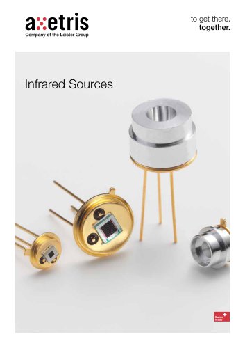
Infrared Sources
12 Pages
-
Infrared Sources EMIRS200
1 Pages
-
EMIRS200
2 Pages
-
EMIRS50 AT06V BT170
8 Pages
-
EMIRS50 AT06V BR26M
8 Pages
-
EMIRS50 AT06V
8 Pages
-
EMIRS50 AT06V BR25M
8 Pages
-
EMIRS50 AT06V BC150
8 Pages
-
MFD BaseFlo Line
2 Pages
-
EMIRS50 AT06V BC150 Series
8 Pages
-
Inductively Coupled Plasma
2 Pages
-
Gas Chromatography
2 Pages
-
Infrared Sources EMIRS50
1 Pages
-
LGDF200 A CH4
8 Pages
-
LGDF200 H HCl
9 Pages
-
FL - Infrared Source EMIRS50
2 Pages
-
Micro-Optics
2 Pages
-
Infrared Sources EMIRS200
12 Pages
-
DS - LGDF200 H NH3
9 Pages
-
DS- LGDF200 A NH3
8 Pages
-
DS - LGDF200 A CO2
8 Pages
-
FL - Axetris MFD Plus
2 Pages
-
FL - LGD F200P2
2 Pages
-
Reflector
4 Pages
-
MEMS Services
2 Pages

