Catalog excerpts
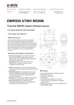
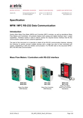
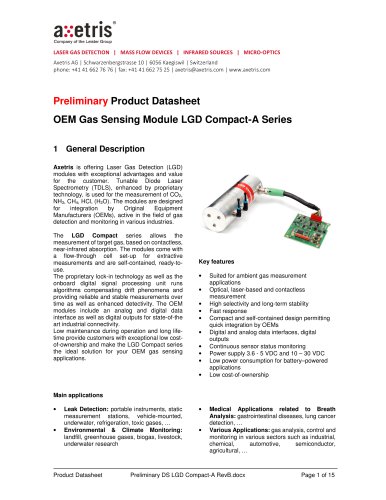
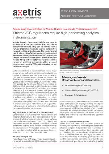
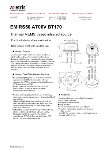
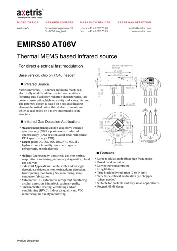
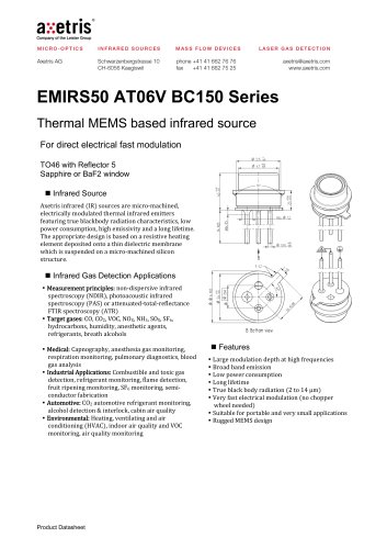
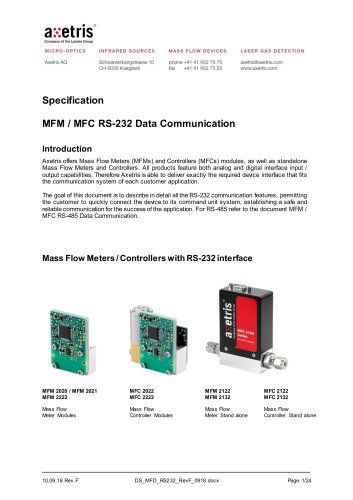
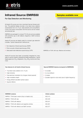
MICRO-OPTICS INFRARED SOURCES LASER GAS DETECTION axetris@axetris.com www.axetris.com - • ® axetris Company of the Leister Group MASS FLOW DEVICES phone +41 41 662 76 76 fax +41 41 662 75 25 For direct electrical fast modulation TO46 header with Reflector 7 ■ Infrared Source Axetris infrared (IR) sources are micro-machined, electrically modulated thermal infrared emitters featuring true blackbody radiation characteristics, low power consumption, high emissivity and a long lifetime. The appropriate design is based on a resistive heating element deposited onto a thin dielectric membrane which is suspended on a micro-machined silicon structure. ■ Infrared Gas Detection Applications • Measurement principles: non-dispersive infrared spectroscopy (NDIR), photoacoustic infrared spectroscopy (PAS) or attenuated-total-reflectance FTIR spectroscopy (ATR) • Target gases: CO, CO2, VOC, NOx, NH3, SOx, SF6, hydrocarbons, humidity, anesthetic agents, refrigerants, breath alcohols • Medical: Capnography, anesthesia gas monitoring, respiration monitoring, pulmonary diagnostics, blood gas analysis • Industrial Applications: Combustible and toxic gas detection, refrigerant monitoring, flame detection, fruit ripening monitoring, SF6 monitoring, semiconductor fabrication • Automotive: CO2 automotive refrigerant monitoring, alcohol detection & interlock, cabin air quality • Environmental: Heating, ventilating and air conditioning (HVAC), indoor air quality and VOC monitoring, air quality monitoring ■ Features • Large modulation depth at high frequencies • Broad band emission • Low power consumption • Long lifetime • True black body radiation (2 to 14 pm) • Very fast electrical modulation (no chopper wheel needed) • Suitable for portable and very small applications • Rugged MEMS design
Open the catalog to page 1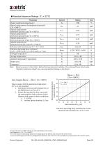
■ Absolute Maximum Ratings (Ta = 22°C) Parameter Note: Emission power in this table is defined by hemispherical radiation. Stress beyond those listed under “absolute maximum ratings” may cause permanent damage to the device. Note: Diagram Rh500C — Rc22 | (Tm = 500°C) How to ensure that the maximum temperature for Tm is not exceeded: 1. Determine electrical cold resistance Rc of the EMIRS device at TA=22°C 2. Ensure that anytime Rh does not exceed the representative limit as shown in this diagram with respect to these conditions: a. f > 10 Hz b. on-time (pulse duration) > 3 ms Cold...
Open the catalog to page 2
■ Ratings at Reference Operation (RO1 Ta = 22°C) Parameter Note: First order on-time model using Ton: First order off-time model using Toff: Vh — t (RO2 input pulse shape) Relative rectangular heater voltage (Vh) pulse with a relative pulse width of 62 ms at 10 Hz (time description of reference operation RO1) Optical response time (relative optical output power Poo) of a rectangular voltage pulse (RO2 conditions) Product Datasheet Recommended frequencies from 10 Hz to 100 Hz Reference Operation: combines lower cut-off frequency of 10 Hz and maximum modulation depth (max-min signal)
Open the catalog to page 3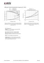
Typical Timing Characteristics Frequency (D = 62%) Relative (to RO) max, min, max-min values of optical output power (POO) versus frequency f with fixed and compensated VH Relative (to RO) electrical drive values heater voltage VH and power PH versus frequency f for compensation Note: Diagrams a, b Relative POO, VH, PH to reference operation (RO) f=10 Hz, rect. pulse D=62% max: maximum value of POO response shape min: minimum value of POO response shape max-min: amplitude calculation of POO resp. shape Fixed VH: same voltage for all frequencies. Compensated VH: for every frequency value,...
Open the catalog to page 4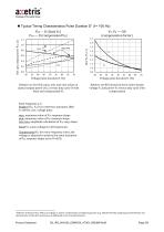
Typical Timing Characteristics Pulse Duration D1 (f = 100 Hz) Poo - - D (fixed Vh) Poo — D (compensated Vh) Voltage pulse duration D (%) Relative (to D=62%) max, min, max-min values of Relative (to RO) electrical drive values heater optical output power (Poo) versus duty cycle D with voltage Vh and power Ph versus duty cycle D for fixed and compensated Vh compensation Note: Diagrams a, b Relative Poo, Vh, Ph to reference operation (RO) f=100 Hz, rect. voltage pulse max: maximum value of Poo response shape min: minimum value of Poo response shape max-min: amplitude calculation of Poo resp....
Open the catalog to page 5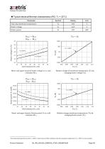
■ Typical electrical/thermal characteristics (RO, Ta = 22°C) Cold resistance Rc22 (H) Mean1 and upper bound of heater voltage Vh vs. cold resistance RC22 Vh (1) Relative change of membrane temperature (Tm) by changing heater voltage (Vh) Mean1 and upper bound of heater power Ph vs. cold resistance RC22 Product Datasheet Recommended operation mode Tm =460°C, which ensures 95% confidence that the maximum temperature Tm = 500°C is not exceeded.
Open the catalog to page 6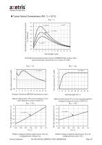
■ Typical Optical Characteristics (RO, Ta = 22°C) Wavelength X (pm) Hemispherical spectral emissive power of EMIRS50 chip surface with a typical emissivity (mean from 2 to 14 pm) of £=0.85 Rel. opt. output power Poo (1) Out output power Poo fmV\D Distance d between EMIRS50 and detector (mm) Optical output power (Poo) versus distance d of a 1 mm2 detection surface at 500°C Tm Vh (1) Relative change of optical output power (Poo) by changing heater voltage (Vh) Ph (1) Relative change of optical output power (Poo) by changing heater power (Ph) Product Datasheet
Open the catalog to page 7
■ Specified Ratings at Test Voltage Vt (on-time > 20 ms, Th = Ta = 22°C) Parameter Note: Other optical output specifications are possible by customer specific requirements (e.g. spectral ranges). Note: Diagram Vt500C — Rc22 | (Tm * 500°C) Defined test voltage Vt for specified ratings: 1. Determine electrical cold resistance Rc22 of the EMIRS device at Ta=22°C 2. Drive the device with Vt for each Rc as shown in this diagram. 3. Ratings are only valid for Tp = Ta = 22°C and after 20 ms on-time. Test voltage Vt versus electrical cold resistance Rc22 at Ta = 22°C Product Datasheet
Open the catalog to page 8All Axetris AG catalogs and technical brochures
-
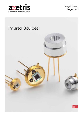
 Infrared Sources
12 Pages
-
 Infrared Sources EMIRS200
1 Pages
-
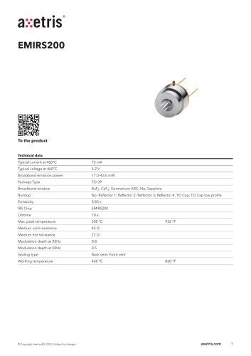 EMIRS200
2 Pages
-
 EMIRS50 AT06V BT170
8 Pages
-
 EMIRS50 AT06V
8 Pages
-
 EMIRS50 AT06V BR25M
8 Pages
-
 EMIRS50 AT06V BC150
8 Pages
-
 MFD BaseFlo Line
2 Pages
-
 EMIRS50 AT06V BC150 Series
8 Pages
-
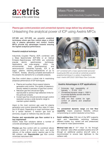 Inductively Coupled Plasma
2 Pages
-
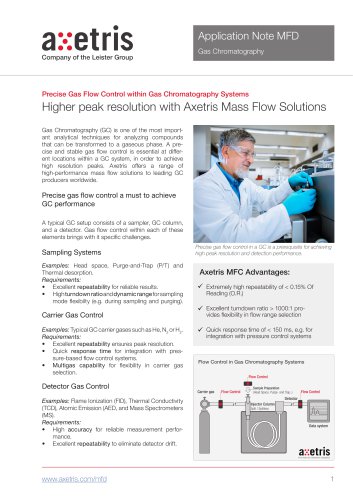 Gas Chromatography
2 Pages
-
 MFM / MFC RS-232
24 Pages
-
 Infrared Sources EMIRS50
1 Pages
-
 LGDF200 A CH4
8 Pages
-
 LGDF200 H HCl
9 Pages
-
 FL - Infrared Source EMIRS50
2 Pages
-
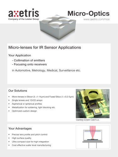
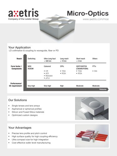 Micro-Optics
2 Pages
-
 Infrared Sources EMIRS200
12 Pages
-
 DS - LGDF200 H NH3
9 Pages
-
 DS- LGDF200 A NH3
8 Pages
-
 DS - LGDF200 A CO2
8 Pages
-
 FL - Axetris MFD Plus
2 Pages
-
 FL - LGD F200P2
2 Pages
-
 Reflector
4 Pages
-
 MEMS Services
2 Pages