
- Catalogs
- Avantec Zerspantechnik GmbH
- data sheet side milling cutter TB18 TN18


data sheet side milling cutter TB18 TN18

data sheet side milling cutter TB18 TN18
Overview
This document provides comprehensive technical specifications, product data, and machining parameters for TB18 and TN18 series side milling cutters. It focuses on precision cutting with tight radial and axial run-out tolerances and the use of 3-side embedding for T-style indexable inserts to ensure stability and accuracy.
1. Product Specifications
1.1 TB18 Side Milling Cutters
TB18 cutters deliver smooth cutting performance using both left and right-hand inserts. They support precise cut widths ranging from 4 to 12 mm. Key dimensions include outer diameter (D), bore diameter (d) with H7 tolerance, cutter height (H), width of cut (B) with h11 tolerance, number of teeth (zz), number of inserts (z), cutting width (ae), weight, and compatible insert types. For example, article 01T.0604.041 features D=63 mm, d=32 mm, H=16 mm, B=32 mm, cut width 4 mm, 4 teeth, weight 0.21 kg, compatible with TN..1302.R/L inserts.
1.2 TN18 Side Milling Cutters
TN18 cutters have similar applications but differ slightly in dimensions and insert compatibility. They also cover cut widths from 4 to 12 mm, with detailed data on diameters, widths, teeth count, weights, and screw length variations depending on the insert type.
2. Insert Types and Designations
The document lists compatible insert types including TC..1102.., TC..1103.., TN..1302.., TN..16T3.., TN..1604.., and TN..1606.. series. Each insert is identified by a designation code and linked to specific machining parameters, facilitating correct selection based on application needs.
3. Machining Parameters and Material Compatibility
3.1 Steel
For steel materials, inserts have defined maximum chip thickness (hmax) and cutting speed (vc) ranges tailored to AV material groups A22 through A16. For instance, TC..1102.. inserts have hmax values from 0.12 to 0.05 mm and cutting speeds ranging from 280-320 m/min down to 80-110 m/min depending on the steel grade.
3.2 Cast Iron
Parameters for cast iron (material groups D21 to D16) are adjusted to suit its machining characteristics, with slightly modified cutting speeds and chip thicknesses to optimize performance.
3.3 Stainless Steels and Non-Ferrous Metals
For stainless steels and non-ferrous metals (groups C12 to E80), cutting speeds are generally lower due to material hardness and machinability differences, with corresponding chip thickness adjustments.
4. Key Features and Recommendations
- Extremely smooth cutting with both left and right-hand inserts.
- Precise control of cut widths from 4 to 12 mm.
- Strict adherence to narrow radial and axial run-out tolerances for high machining accuracy.
- 3-side embedding of T-style indexable inserts enhances tool stability and cutting precision.
- Screw length varies depending on insert type and must be considered during tool assembly.
- Machining parameters (chip thickness and cutting speed) are matched to specific material groups to optimize tool life and machining quality.
5. Summary of Tables and Data
The document includes extensive tables detailing cutter dimensions, weights, insert compatibility, and machining parameters. These serve as a practical reference for selecting the appropriate cutter and insert combination based on the workpiece material and desired cutting conditions.
6. Machining Parameters Overview for Specific Tools
For tool models SKY77 TNAW 160608 SL-28 and SR-28, maximum cutting depths (hmax) range from 0.07 to 0.20 mm. Cutting speeds (vc) vary widely from 60 to 1000 m/min, segmented into intervals such as 60-100, 100-140, 120-200, 140-150, 280-450, 450-650, and 650-1000 m/min, depending on the operation and material.
7. Matching Machining Parameters with AV Material Groups
Insert codes (e.g., TC..1102..., TC..1103..., TN..11T3..., TN..1302..., TN..1604..., TN..1606...) are linked to AV material group codes (TX208, TX215), ensuring compatibility between machining parameters and material types. Some inserts require different screw lengths, indicated by an asterisk, which must be accounted for during setup.
8. Insert and Tool Specifications
Insert shapes and sizes are specified, including diameters (Ø) of 6.35, 8, and 9.52 mm and thicknesses (s) ranging from 2.6 to 6.4 mm for various TC and TN insert types and sizes (3, 11, 13, 16, 02, 03, T3, 04, 06).
9. Application Notes
The parameters and inserts described are intended primarily for side milling operations, emphasizing precision and efficiency.
10. Critical Information and Recommendations
- Ensure correct matching of machining parameters with AV material group codes for optimal tool performance and longevity.
- Account for screw length variations for certain inserts during tool assembly.
- Adhere strictly to specified maximum cutting depths and cutting speeds to maintain tool life and machining quality.
Overall, this document serves as a detailed technical guide for selecting and applying TB18 and TN18 side milling cutters and their compatible inserts, enabling efficient, precise milling across a range of materials.
Catalog excerpts

SIDE MILLING CUT TERS SIDE MILLING CUTTERS TB18 Extremely smooth cutting through left and right hand inserts – highly precise widths of cut from 4–12 mm Complies with narrow radial and axial run out tolerances 3-side embedding of the T-style indexable insert
Open the catalog to page 1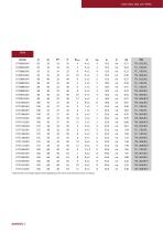
SIDE MILLING CUT TERS * Note that the screw length required varies depending on the insert used. Other dimensions on request.
Open the catalog to page 2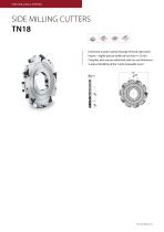
SIDE MILLING CUT TERS SIDE MILLING CUTTERS TN18 Extremely smooth cutting through left and right hand inserts – highly precise widths of cut from 4–12 mm Complies with narrow radial and axial run out tolerances 3-side embedding of the T-style indexable insert D dH7
Open the catalog to page 3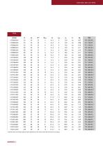
SIDE MILLING CUT TERS * Note that the screw length required varies depending on the insert used. Other dimensions on request.
Open the catalog to page 4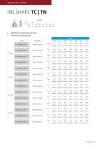
SIDE MILLING CUT TERS Matching of machining parameters with the AV material groups Steel Article
Open the catalog to page 5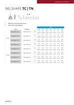
SIDE MILLING CUT TERS Matching of machining parameters with the AV material groups Steel Article
Open the catalog to page 6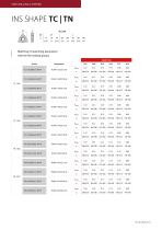
SIDE MILLING CUT TERS Matching of machining parameters with the AV material groups Cast iron Article
Open the catalog to page 7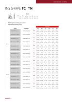
SIDE MILLING CUT TERS Matching of machining parameters with the AV material groups Cast iron Article TN.1604.004.41 SKY77
Open the catalog to page 8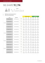
SIDE MILLING CUT TERS Matching of machining parameters with the AV material groups Stainless steels Article
Open the catalog to page 9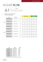
SIDE MILLING CUT TERS Matching of machining parameters with the AV material groups Stainless steels Article * Note that the screw length required varies depending on the insert used
Open the catalog to page 10All Avantec Zerspantechnik GmbH catalogs and technical brochures
 data sheet TZ18
3 Pages
 data sheet High Feed UD90
5 Pages
 data sheet multiring FM90
3 Pages
 data sheet multiring MM90
2 Pages
 Data sheet Multiring CM90
2 Pages
 data sheet multiring EM90
4 Pages
 Data Sheet Broaching Tool
2 Pages
 Boger Benz product catalog
40 Pages
 MILLING TOOLS CATALOG
156 Pages


- Steel milling cutter
- Milling tool with replaceable insert
- Metal milling cutter
- Clamping milling cutter
- Milling cutter with cylindrical shank
- End mill
- Cast iron milling cutter
- Face milling cutter
- Shell-end milling cutter
- Indexable insert milling cutter
- Cutting milling cutter
- High-performance milling cutter
- Helix angle milling cutter
- Roughing milling cutter
- Shoulder milling cutter
- Slot milling tool
- Stainless steel milling cutter
- High-speed milling cutter
- High-precision milling cutter