Catalog excerpts
The 4-pin MOST Optical Receiver (MIR3 02) is a highly integrated CMOS IC combined with a high speed PIN - diode designed to receive up to 25Mbit/s optical data which is bi-phase coded at up to 50Mbaud and convert this optical data to a TTL compatible data stream.This high performance, low cost, CMOS receiver consists of a low noise transimpedance amplier and comparator in the data path. A timer circuit puts the part into a low power mode if optical data is not received for 10εs (typ.). During the low power mode, the PIN diode is still being observed and if activity is detected, the IC will resume full power operation within 3.5ms (typ.).A STATUS-pin indicates if modulated light is received (Light on -> STATUS = low). With the STATUS-pin the power supply of the whole MOST device can be switched ON. Excellent solution for converting high speed data from Plastic Optical Fiber (POF) to digital output. ∑ High speed receiver up to 50 MBaud (25Mbit/s net data rate) ∑ TTL Data Output (Light to Logic Function) ∑ Network activity sensing during ZeroPower Mode (I > CC <10A) բȑ BUS Activity Status Output ∑ Good 650nm sensitivity for working in a low attenuation range of PMMA Fiber ∑ Low cost > ∑ Optical Receiver for MOST Systems > IC Revisionpackage typeOptical Sensitivity device marking JCAI-24.5 dBmdate code,MIR3 02 >
Open the catalog to page 1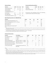
ParameterSymbolMinMaxUnit ParameterSymbolMinMaxUnit Supply VoltageV Storage Temperature RangeT > STG -40100CJunction TemperatureT > CC 4.755.25VOperating Temperature Range T > J -40100аCSoldering Temperature (>2.5 mm from case bottom t5s)T > A -4085ðC > S -235CPower Dissipation P > TOT -300mWPower Supply VoltageV All the data in this specication refers to the operating conditions above unless otherwise stated. > CCMax -0.56.0VDC Current To Any Pin Except PowerI > I/OMax -б10mA > ParameterSymbolMinTypMaxUnit Maximum Photosensitivity Wavelength (T > A =25C)ЎS > max -850-nmPhotosensitivity...
Open the catalog to page 2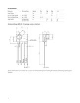
ParameterTest ConditionsSymbolMinTypMaxUnit Supply VoltageV > CC 4.755.05.25VLow Level Output VoltageI > OL = 2.4mAV > OL --0.4VHigh Level Output VoltageI > OH = 2.4mAV > OH V > CC -1.0--VSupply CurrentFull power mode Low power modeI > CC -18.5 522 10mA A > Device information (Lot number etc.) is given on CAI backside by laser marking (for details see drawing marking speci-cation). 3 >
Open the catalog to page 3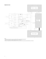
Notes:1. Place these components as close as possible to their corresponding pins of the FOT. 2. Values can change due to dierent light output power of the LED. 3. This is just a proposal for the Rext application. There can be used also other circuits to switch Rext from 15K to 30K 4 >
Open the catalog to page 4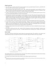
∑ The 100nF bypass capacitors of the FOTs must be located as close as possible between the pins V > CC and GND of the FOTs. Use ceramic caps and tantalum caps with low ESR. ∑ Also the inductor/ ferrite bead (receiver) and the -3dB - control circuit (transmitter) must be placed as close as possible to the FOTs. We prefer ferrite beads (e.g. type 74279214 Wrth Elektronik) since the D.C. resistance is very low. In case other inductors are used, the D.C. resistance should be less than 3Ohm. 좈 For EMC, a ferrite bead should be connected to the power supply, close to the transmitter and the...
Open the catalog to page 5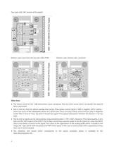
Top Layer with 180˚ version of the pigtail: Bottom Layer (seen from the top side of the PCB):Bottom Layer: Bottom side / positions > ∑ The shown circuit for the 3dB attenuation is just a proposal. Also any other circuit which can double the value of Rext is permitted. ֢ȑ Due to the fact that the optical average level jumps if the power control signal (/-3dB) is toggled, LOCK/ coding errors can occur at the subsequent device for a short time. This is not very critical, since it occurs only in diagnosis mode. After a time of 10ms, the device should lock again if the optical attenuation...
Open the catalog to page 6
The information herein is given to describe certain components and shall not be considered as a guarantee of characteristics.Terms of delivery and rights to technical change reserved.We hereby disclaim any and all warranties, including but not limited to warranties of non-infringement, regarding circuits, descriptions and charts stated herein. > Due to technical requirements components may contain dangerous substances. For information on the types in- question please contact your nearest Avago Technologies Oce. Avago Technologies Components may only be used in life-support devices or...
Open the catalog to page 7All Avago Technologies catalogs and technical brochures
-
AFCD-V84LP
1 Pages
-
BCM4778
2 Pages
-
AFBR-57H5MZ
29 Pages
-
ASMB-UTF0-0D20B
12 Pages
-
ASMT-YTD7-0AA02
15 Pages
-
ASMT-YTC7-0AA02
15 Pages
-
ASMT-RF45-AN002
8 Pages
-
Optical Sensor
64 Pages
Archived catalogs
-
WLAN Low-Noise Amplifier
10 Pages
-
Optoisolation Products
58 Pages
-
125 Megabaud Versatile Link
12 Pages
-
LED Solutions
96 Pages


