
- Catalogs
- Avago Technologies
- ASMT-YTD7-0AA02

ASMT-YTD7-0AA02

ASMT-YTD7-0AA02
Catalog excerpts
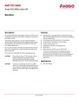
AVOGO TECHNOLOGIES ASMT-YTD7-0AA02 Tricolor PLCC6 White Surface LED Data Sheet Description This family of SMT LEDs is packaged in the form of PLCC-6 with a separate heat path for each LED die, enabling it to be driven at a higher current. Individually addressable pin-outs give higher flexibility in circuitry design. With closely matched radiation pattern along the package's X-axis, these LEDs are suitable for indoor full color display applications. For easy pick and place, the LEDs are shipped in tape and reel. Every reel is shipped from a single intensity and color bin for better uniformity. These LEDs are compatible with reflow soldering process. CAUTION These LEDs are Class 1C ESD sensitive. Please observe appropriate precautions during handling and processing. Refer to Avago Application Note AN-1142 for additional details. CAUTION Customers should keep the LED in the MBB when not in use because prolonged exposure to the environment might cause the silver-plated leads to tarnish, which might cause difficulties in soldering. Features ■ Standard PLCC-6 package (Plastic Leaded Chip Carrier) with individual addressable pin-out for higher flexibility of driving configuration ■ LED package with diffused silicone encapsulation ■ Using AlInGaP and InGaN dice technologies ■ Typical viewing angle 110° ■ Compatible with reflow soldering process ■ JEDEC MSL 3 ■ Water-Resistance (IPX6*) per IEC 60529:2001 * The test is conducted at the component level by mounting the components on the PCB with proper porting to protect the leads. Customers should perform the necessary tests on the components for their final applications. Applications ■ Full color display
Open the catalog to page 1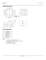
Package Dimensions Package Marking Cathode (Blue) Cathode (Green) Anode (Green) Anode (Blue) All dimensions are in millimeters (mm). Unless otherwise specified, tolerance is ± 0.20 mm. Encapsulation = silicone. Terminal finish = silver plating. Avago Technol
Open the catalog to page 2
Table 1. Absolute Maximum Ratings (Tj = 25 °C) Table 1. Absolute Maximum Ratings (Tj = 25 °C) a. Tolerance = ±0.1V. b. Indicates product final testing condition. Long-term reverse bias is not recommended.
Open the catalog to page 3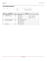
Part Numbering System Part Numbering System ASMT-YTD7 x1 Code
Open the catalog to page 4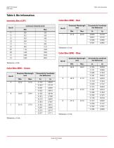
Table 4. Bin Information Intensity Bins (CAT) Color Bins (BIN) - Red Bin ID Tolerance: ±1 nm. Color Bins (BIN) - Blue Tolerance: ±12% Color Bins (BIN) - Green Bin ID Tolerance: ±1 nm. Tolerance: ±1 nm. Avago Technologies - 5 -
Open the catalog to page 5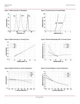
Figure 1 Relative Intensity vs. Wavelength Figure 2 Forward Current vs. Forward Voltage RELATIVE INTENSITY 7 DOMINANT WAVELENGTH SHIFT - nm RELATIVE INTENSITY Figure 4 Dominant Wavelength Shift vs. Forward Current Figure 5 Relative Intensity vs. Junction Temperature Figure 6 Forward Voltage vs. Junction Temperature FORWARD VOLTAGE SHIFT - V RELATIVE INTENSITY Figure 3 Relative Intensity vs. Forward Current
Open the catalog to page 6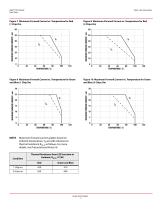
Figure 7 Maximum Forward Current vs. Temperature for Red (1 Chip On) Figure 8 Maximum Forward Current vs. Temperature for Red (3 Chips On) 60 MAXIMUM FORWARD CURRENT - mA MAXIMUM FORWARD CURRENT - mA 30 MAXIMUM FORWARD CURRENT - mA MAXIMUM FORWARD CURRENT - mA Figure 10 Maximum Forward Current vs. Temperature for Green and Blue (3 Chips On) Figure 9 Maximum Forward Current vs. Temperature for Green and Blue (1 Chip On) Thermal Resistance from LED Junction to Ambient, RJ-A (°C/W) Red Maximum forward current graphs based on ambient temperature, TA are with reference to thermal resistance RJ-A...
Open the catalog to page 7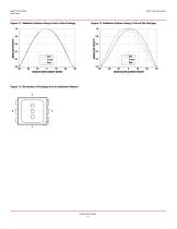
Figure 11 Radiation Pattern Along X-Axis of the Package Figure 12 Radiation Pattern Along Y-Axis of the Package NORMALIZED INTENSITY NORMALIZED INTENSITY Figure 13 Illustration of Package Axis for Radiation Pattern
Open the catalog to page 8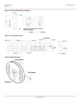
Figure 14 Recommended Soldering Land Pattern 2.30 0.50 Maximize the size of copper pad of PIN 1, PIN 4, PIN5 for better heat dissipation. Copper pad Solder mask Figure 15 Carrier Tape Dimensions Package Marking 4.00 ±0.10 Figure 16 Reeling Orientation USER FEED DIRECTION PACKAGE MARKING PRINTED LABEL Avago Technologi
Open the catalog to page 9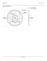
Avago Tech
Open the catalog to page 10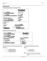
Packing Label Packing Label (i) Standard label (attached on moisture barrier bag) (1P) Item: Part Number I (9D)MFG Date: Manufacturing Date llllllllllllllllllllllllllllllllllll BIN: Color Bin (P) Customer Item: mm in (V) Vendor ID: mm in DeptID: (9D) Date Code: Date Code min iiiiiiiiiiiiiiiiiiiiii ilium Made In: Country of Origin (ii) Baby label (attached on plastic reel) (1P) PART #: Part Number iiiiii iiiiiiiiiiiiiiiiiiiiii iiiiiiiiiiiiiiii (1T) LOT #: Lot Number IIIIII IIIIIIIIIIIIIIIIIIIIII IIIIIIIIIIIIIIII (9D)MFG DATE: Manufacturing Date miimiii ilium C/O: Country of Origin AVclGO TECHNOLOGIES BABY...
Open the catalog to page 11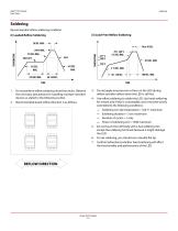
Soldering Recommended reflow soldering condition (ii) Lead-Free Reflow Soldering (i) Leaded Reflow Soldering 20 SEC. MAX. Do not perform reflow soldering more than twice. Observe the necessary precautions for handling moisture-sensitive devices as stated in the following section. Do not apply any pressure or force on the LED during reflow and after reflow when the LED is still hot. Use reflow soldering to solder the LED. Use hand soldering for rework only if this is unavoidable, and it must be strictly controlled to the following conditions: Recommended board reflow direction is as follows. Soldering...
Open the catalog to page 12
Precautionary Notes Precautionary Notes 1. Handling precautions The encapsulation material of the LED is made of silicone for better product reliability. Compared to epoxy encapsulant that is hard and brittle, silicone is softer and flexible. Observe pecial handling precautions during assembly of silicone encapsulated LED products. Failure to comply might lead to damage and premature failure of the LED. Refer to Application Note AN5288, Silicone Encapsulation for LED: Advantages and Handling Precautions for more information. a. Do not poke sharp objects into the silicone encapsulant. Sharp objects,...
Open the catalog to page 13
Precautionary Notes The complication of using this formula lies in TA and RJ-A. Actual TA is sometimes subjective and hard to determine. RJ-A varies from system to system depending on design and is usually not known. The drive current of the LED must not exceed the maximum allowable limit across temperature as stated in the data sheet. Constant current driving is recommended to ensure consistent performance. LEDs exhibit slightly different characteristics at different drive currents, which might result in larger variations in their performance (i.e., intensity, wavelength, and forward voltage)....
Open the catalog to page 14All Avago Technologies catalogs and technical brochures
 AFCD-V84LP
1 Page
 BCM4778
2 Pages
 AFBR-57H5MZ
29 Pages
 ASMB-UTF0-0D20B
12 Pages
 ASMT-YTC7-0AA02
15 Pages
 ASMT-RF45-AN002
8 Pages
 Optical Sensor
64 Pages


Archived catalogs
 WLAN Low-Noise Amplifier
10 Pages
 Optoisolation Products
58 Pages
 125 Megabaud Versatile Link
12 Pages
 LED Solutions
96 Pages


- Angular encoder
- Incremental encoder
- Incremental rotary encoder
- Switching relay
- Absolute rotary encoder
- Signal amplifying integrated circuit
- Electronic display panel
- Optical rotary encoder
- Transceiver module
- Electronic filter
- Magnetic rotary encoder
- Power amplifying integrated circuit
- Diode
- Visible LED
- Transistor module
- Solid state relay
- GNSS receiver
- Ethernet transceiver
- Rectifier diode