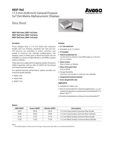
Catalog excerpts
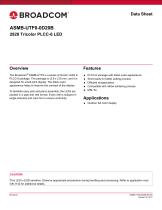
Data Sheet Overview The Broadcom® ASMB-UTF0 is a series of tricolor LEDs in PLCC-6 package. The package is (2.8 x 2.8) mm, and it is designed for small pitch display. The black outer appearance helps to improve the contrast of the display. To facilitate easy pick-and-place assembly, the LEDs are packed in a tape and reel format. Every reel is shipped in single intensity and color bin to ensure uniformity. Features ■ PLCC-6 package with black outer appearance ■ Short leads for better potting process ■ Diffused encapsulation ■ Compatible with reflow soldering process ■ MSL 5a Applications ■ Outdoor full color display CAUTION! This LED is ESD sensitive. Observe appropriate precautions during handling and processing. Refer to application note AN-1142 for additional details.
Open the catalog to page 1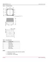
ASMB-UTF0-0D20B Data Sheet 2828 Tricolor PLCC-6 LED Figure 1: Package Drawing ASMB-UTF0-0D20B Data Sheet 2828 Tricolor PLCC-6 LED 1. Tolerance is ±0.20 mm unless otherwise specified. 3. Terminal finish = silver plating.
Open the catalog to page 2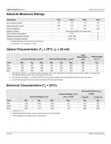
ASMB-UTF0-0D20B Data Sheet 2828 Tricolor PLCC-6 LED a. Tolerance =± 0.1V. b. Indicates product final testing. Long term reverse bias is not recommended. c. Thermal resistance from LED junction to solder point.
Open the catalog to page 3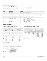
ASMB-UTF0-0D20B Data Sheet 2828 Tricolor PLCC-6 LED Tolerance = ±1 nm Tolerance = ±12% Example of bin information on reel and packaging label: CAT: J2 R2 G2 — Red intensity bin J2 — Green intensity bin R2 — Blue intensity G2 BIN: GB — Green color bin G
Open the catalog to page 4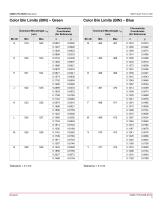
ASMB-UTF0-0D20B Data Sheet 2828 Tricolor PLCC-6 LED Tolerance = ±1 nm Tolerance = ±1 nm Broadcom
Open the catalog to page 5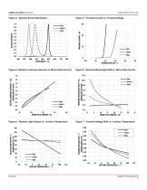
Figure 3: Forward Current vs. Forward Voltage RELATIVE INTENSITY Figure 2: Spectral Power Distribution Figure 4: Relative Luminous Intensity vs. Mono Pulse Current 10 20 30 MONO PULSE CURRENT- mA Figure 6: Relative Light Output vs. Junction Temperature 10 15 20 25 MONO PULSE CURRENT - mA FORWARD VOLTAGE SHIFT - V (NORMALIZED AT 25°C) Figure 7: Forward Voltage Shift vs. Junction Temperature 160 RELATIVE LIGHT OUTPUT - % (NORMALIZED AT 25°C) Figure 5: Dominant Wavelength Shift vs. Mono Pulse Current DOMINANT WAVELENGTH SHIFT - nm (NORMALIZED AT 20mA) 1.8 RELATIVE LUMINOUS INTENSITY - mcd...
Open the catalog to page 6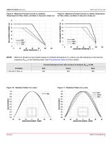
Figure 8: Maximum Forward Current vs. Ambient Temperature for Red, Green, and Blue (1 chip and 3 chips on) Figure 9: Maximum Forward Current vs. Solder Temperature for Red, Green, and Blue (1 chip and 3 chips on) 40 60 80 SOLDER POINT TEMPERATURE, Ts - °C Maximum forward current graphs based on ambient temperature (TA) above are with reference to the thermal resistance RθJ-A in the following table. See Precautionary Notes for more details. Thermal Resistance from LED Junction to Ambient, RθJ-A (°C/W) Condition Figure 10: Radiation Pattern for x-Axis Figure 11: Radiation Pattern for y-Axis...
Open the catalog to page 7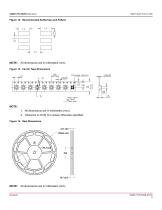
ASMB-UTF0-0D20B Data Sheet 2828 Tricolor PLCC-6 LED Figure 12: Recommended Soldering Land Pattern ASMB-UTF0-0D20B Data Sheet 2828 Tricolor PLCC-6 LED H 1-3 I— NOTE: All dimensions are in millimeters (mm). Figure 13: Carrier Tape Dimensions NOTE: 1. All dimensions are in millimeters (mm). 2. Tolerance is ±0.20 mm unless otherwise specified.
Open the catalog to page 8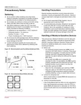
Precautionary Notes Handling Precautions Do not perform reflow soldering more than twice. Observe necessary precautions of handling moisturesensitive devices as stated in the following section. Do not apply any pressure or force on the LED during reflow and after reflow when the LED is still hot. Use reflow soldering to solder the LED. Use hand soldering only for rework if unavoidable, but it must be strictly controlled to following conditions: – Soldering iron tip temperature = 315°C maximum – Soldering duration = 3s maximum – Number of cycles = 1 only – Power of soldering iron = 50W...
Open the catalog to page 9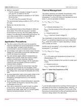
ASMB-UTF0-0D20B Data Sheet 2828 Tricolor PLCC-6 LED ■ Baking is required if: - The HIC indicator indicates a change in color for 10% and 5%, as stated on the HIC. - The LEDs are exposed to conditions of >30°C/60% RH at any time. - The LED's floor life exceeded 24 hours. The recommended baking condition is: 65°C ± 5°C for 24 hours. Baking can only be done once. ■ Storage: The soldering terminals of these Broadcom LEDs are silver plated. If the LEDs are exposed in ambient environments for too long, the silver plating might be oxidized, thus affecting its solderability performance. As such,...
Open the catalog to page 10
Eye Safety Precautions LEDs may pose optical hazards when in operation. Do not look directly at operating LEDs because it might be harmful to the eyes. For safety reasons, use appropriate shielding or personal protective equipment.
Open the catalog to page 11
Disclaimer Broadcom's products and software are not specifically designed, manufactured, or authorized for sale as parts, components, or assemblies for the planning, construction, maintenance, or direct operation of a nuclear facility or for use in medical devices or applications. The customer is solely responsible, and waives all rights to make claims against Broadcom or its suppliers, for all loss, damage, expense, or liability in connection with such use. Broadcom, the pulse logo, Connecting everything, Avago Technologies, Avago, and the A logo are among the trademarks of Broadcom and/or...
Open the catalog to page 12All Avago Technologies catalogs and technical brochures
-
AFCD-V84LP
1 Pages
-
BCM4778
2 Pages
-
AFBR-57H5MZ
29 Pages
-
ASMT-YTD7-0AA02
15 Pages
-
ASMT-YTC7-0AA02
15 Pages
-
ASMT-RF45-AN002
8 Pages
-
Optical Sensor
64 Pages
Archived catalogs
-
WLAN Low-Noise Amplifier
10 Pages
-
Optoisolation Products
58 Pages
-
125 Megabaud Versatile Link
12 Pages
-
LED Solutions
96 Pages


