Catalog excerpts

Data Sheet AFBR-57H5MZ 64GFC SFP56 for Multi-Mode Optical Fiber Digital Diagnostic SFP, 850 nm, 64G/32G/16G Description The Broadcom® AFBR-57H5MZ optical transceiver supports high-speed serial links over multi-mode optical fiber at signaling rates up to 57.8 Gb/s PAM4 (the serial line rate of 64GFC). The product is compliant with Small Form Pluggable SFP+ industry agreements for mechanical and low speed electrical specifications. High-speed electrical and optical specifications are compliant with ANSI Fibre Channel FC-PI-7. The AFBR-57H5MZ is a multi-rate 850-nm transceiver that ensures compliance with FC-PI-7 64GFC, 32GFC, and 16GFC specifications. Per the requirements of 64GFC, internal clock and data recovery circuits (CDRs) are present on both electrical input and electrical output of this transceiver. These CDRs lock at 57.8-Gb/s PAM4, 28.05-Gb/s NRZ and 14.025-Gb/s NRZ (64GFC, 32GFC, and 16GFC) accomplished by using two Rate Select inputs and I2C to configure transmit and receive sides. Digital diagnostic monitoring information (DMI) is present in the AFBR-57H5MZ per the requirements of SFF-8472, providing real time monitoring information of transceiver laser, receiver and environment conditions over an SFF-8431 I2C interface. AFCT-57G5PZ: 1310-nm SFP for 32G/16G/8G Fibre Channel AFBR-57G5PZ: 850-nm SFP for 32G/16G/8G Fibre Channel AFBR-57F5PZ: 850-nm SFP for 16G/8G/4G Fibre Channel AFCT-57F5APZ: 1310-nm SFP for 16G/8G/4G Fibre Channel Compliant to RoHS directives Broadcom’s high-performance 850-nm Vertical Cavity Surface Emitting Laser (VCSEL) and PiN diode Class 1 eye safe per IEC60825-1 and CDRH Wide temperature range (0°C to 75°C) LC duplex connector optical interface conforming to ANSI TIA/EIA604-10 (FOCIS 10A) Diagnostic features per SFF-8472, “Diagnostic Monitoring Interface for Optical Transceivers” Enhanced operational features including EWRAP, OWRAP, and adaptive electrical EQ/emphasis settings Integrated PRBS generator and bit error rate checker Real time monitoring of the following: – Transmitter average optical power – Received average optical power – Laser bias current – Temperature – Supply voltage – Power-on hours SFP+ mechanical specifications per SFF-8432 SFP+ compliant low-speed interface per SFF-8419 Fibre Channel FC-PI-7 compliant high-speed optical and electrical interface Fibre Channel switches Fibre Channel host bus adapters Fibre Channel RAID controllers Port-side connections Inter-switch or int
Open the catalog to page 1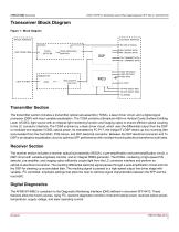
64GFC SFP56 for Multi-Mode Optical Fiber Digital Diagnostic SFP, 850 nm, 64G/32G/16G Transceiver Block Diagram Figure 1: Block Diagram ELECTRICAL INTERFACE OPTICAL INTERFACE RECEIVER LIGHT FROM FIBER TRANS -IMPEDANCE AMPLIFIER TRANSMITTER LIGHT TO FIBER BIAS & SAFETY CIRCUITRY RD+ (RECEIVE DATA) RD- (RECEIVE DATA) TD+ (TRANSMIT DATA) TD- (TRANSMIT DATA) MOD -DEF2(SDA) MOD -DEF1(SCL) MOD -DEF0 TX_FAULT TX RATE SELECT RS(1) RX RATE SELECT RS(0) TX_DISABLE Transmitter Section The transmitter section includes a transmitter optical sub-assembly (TOSA), a laser driver circuit, and a digital...
Open the catalog to page 2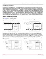
64GFC SFP56 for Multi-Mode Optical Fiber Digital Diagnostic SFP, 850 nm, 64G/32G/16G Low-Speed Interfaces Conventional low-speed interface I/Os are available as defined in SFF-8431 to manage coarse and fine functions of the optical transceiver. On the transmit side, a Tx_DISABLE input is provided for the host to turn on and off the outgoing optical signal. A transmitter rate select control input pin, Tx_RATE, and I2C controls are provided to configure the transmitter stages for 64GFC, 32GFC, or 16GFC operation (logic HIGH reserved for 64GFC and 32GFC, logic LOW reserved for 16GFC). A...
Open the catalog to page 3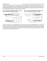
64GFC SFP56 for Multi-Mode Optical Fiber Digital Diagnostic SFP, 850 nm, 64G/32G/16G The electrical SFP input stage (TD +/–) has been enhanced with adaptive EQ, which optimizes the transceiver’s input equalization settings without host control. The SFP electrical output stage (RD+/–) has been enhanced with variable output emphasis features to allow host control and optimization of the receiver’s output settings. The host can then select, in situ, the most appropriate SFP setting for a given interconnect scenario. TOSA Laser Driver Figure 7: Programmable PRBS Pattern Generator and Bit Error...
Open the catalog to page 4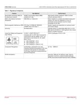
64GFC SFP56 for Multi-Mode Optical Fiber Digital Diagnostic SFP, 850 nm, 64G/32G/16G Table 1: Regulatory Compliance Feature Test Method Electrostatic Discharge (ESD) to the Electrical Contacts JEDEC Human Body Model (HBM) (JESD22-A114-B) High-speed contacts withstand 1000V. All other contacts withstand 2000 V. ESD to the Optical Connector Receptacle When installed in a properly grounded housing and chassis, the units are subjected to 15-kV air discharges during operation and 8-kV direct discharges to the case. Electromagnetic Interference (EMI) FCC Part 15 CENELEC EN55022 (CISPR 22A) VCCI...
Open the catalog to page 5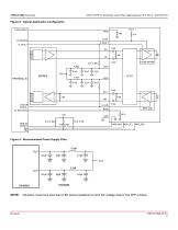
64GFC SFP56 for Multi-Mode Optical Fiber Digital Diagnostic SFP, 850 nm, 64G/32G/16G Figure 8: Typical Application Configuration Tx Rate Select LOSS OF SIGNAL Rx Rate Select LASER DRIVER Figure 9: Recommended Power Supply Filter Inductors must have less than 0.5Ω series resistance to limit the voltage drop to the SFP module.
Open the catalog to page 6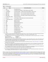
64GFC SFP56 for Multi-Mode Optical Fiber Digital Diagnostic SFP, 850 nm, 64G/32G/16G Transmitter Ground Transmitter Fault Indication - High indicates a fault condition Transmitter Disable - Module optical output disables on high or open Module Definition 2 - Two wire serial ID interface data line (SDA) Module Definition 1 - Two wire serial ID interface clock line (SCL) Module Definition 0 - Grounded in module (module present indicator) Receiver Rate Select Loss of Signal - High indicates loss of received optical signal Transmitter Rate Select Receiver Ground Receiver Ground Inverse Received...
Open the catalog to page 7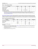
64GFC SFP56 for Multi-Mode Optical Fiber Digital Diagnostic SFP, 850 nm, 64G/32G/16G Table 3: Absolute Maximum Ratings Parameter Storage Temperature Relative Humidity Supply Voltage Low Speed Input Voltage Low Speed Output Current a. Absolute maximum ratings are those values beyond which damage to the device may occur if these limits are exceeded for other than a short period of time. Refer to the reliability data sheet for specific reliability performance. Between the absolute maximum ratings and the Recommended Operating Conditions, functional performance is not intended, device...
Open the catalog to page 8All Avago Technologies catalogs and technical brochures
-
AFCD-V84LP
1 Pages
-
BCM4778
2 Pages
-
ASMB-UTF0-0D20B
12 Pages
-
ASMT-YTD7-0AA02
15 Pages
-
ASMT-YTC7-0AA02
15 Pages
-
ASMT-RF45-AN002
8 Pages
-
Optical Sensor
64 Pages
Archived catalogs
-
WLAN Low-Noise Amplifier
10 Pages
-
Optoisolation Products
58 Pages
-
125 Megabaud Versatile Link
12 Pages
-
LED Solutions
96 Pages


