Catalog excerpts
AEDB-9140 Series Three Channel Optical Incremental Encoder Modules with Codewheel, 100 CPR to 500 CPR Data Sheet The AEDB-9140 series are three channel optical incremental encoder modules oered with a codewheel. When used with a codewheel, these low cost modules detect rotary position. Each module consists of a lensed LED source and a detector IC enclosed in a small plastic package. Due to a highly collimated light source and a unique photodetector array, these modules are extremely tolerant to mounting misalignment. • Two Channel Quadrature Output with Index Pulse The AEDB-9140 has two channel quadrature outputs plus a third channel index output. This index output is a 90 electrical degree high true index pulse which is generated once for each full rotation of the codewheel. The AEDB-9140 is designed for use with a codewheel which has an optical radius of 11.00 mm (0.433 inch). The quadrature signals and the index pulse are accessed through five 0.46 mm square pins located on 1.27 mm(pitch) centers. The AEDB-9140 provide sophisticated motion control detection at a low cost, making them ideal for high volume applications. Typical applications include printers, plotters, tape drives, and industrial and factory automation equipment. • Resolution from 100 CPR to 500 CPR (Counts Per Revolution) • Low Cost • Easy to Mount • No Signal Adjustment required • Small Size • TTL Compatible • Single 5V Supply Note: Avago Technologies encoders are not recommended for use in safety critical applications. Eg. ABS braking systems, power steering, life support systems and critical care medical equipment. Please contact sales representative if more clarication is needed.
Open the catalog to page 1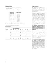
Ordering Information Theory of Operation The AEDB-9140 are emitter/detector modules. Coupled with a codewheel, these modules translate the rotary motion of a shaft into a three-channel digital output. Resolutions (Cycle/Rev) Shaft Diameter* As seen in Figure 1, the modules contain a single Light Emitting Diode (LED) as its light source. The light is collimated into a parallel beam by means of a single polycarbonate lens located directly over the LED. Opposite the emitter is the integrated detector circuit. This IC consists of multiple sets of photodetectors and the signal processing...
Open the catalog to page 2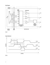
Block Diagram RESISTOR VCC 4 PHOTO DIODES SIGNAL PROCESSING CIRCUITRY EMITTER SECTION DETECTOR SECTION Output Waveforms
Open the catalog to page 3
Denitions Note: Refer to Figure 2 Count (N): The number of bar and window pairs or counts per revolution (CPR) of the codewheel. State Width Error (ΔS): The deviation, in electrical degrees, of each state width from its ideal value of 90°e. One Cycle (C): 360 electrical degrees (°e), 1 bar and window pair. Phase (f ): The number of electrical degrees between the center of the high state of channel A and the center of the high state of channel B. One Shaft Rotation: 360 mechanical degrees, N cycles. Position Error (ΔΘ): The normalized angular dierence between the actual shaft position and...
Open the catalog to page 4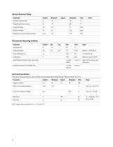
Absolute Maximum Ratings Parameter Storage Temperature Operating Temperature Supply Voltage Output Voltage Output Current per Channel, Iout Supply Voltage Load Capacitance Frequency Recommended Operating Conditions Typ. Shaft Perpendicularity Plus Axial Play Refer to Mounting Consideration Shaft Eccentricity Plus Radial Play Electrical Characteristics Electrical Characteristics Over the Recommended Operating Range. Typical Values at 25°C. Parameter Supply Current High Level Output Voltage Low Level Output Voltage Rise Time Fall Time Note: Typical values specied at Vcc = 5.0 V and 25 °C
Open the catalog to page 5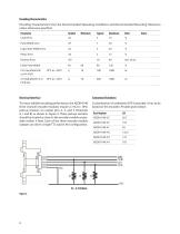
Encoding Characteristics Encoding Characteristics Over the Recommended Operating Conditions and Recommended Mounting Tolerances unless otherwise specified. Parameter Symbol Minimum Typical Maximum Units Notes Pulse Width Error AP 7 30 °e Logic State Width Error AS 5 30 °e Phase Error A<|> 2 15 °e Position Error A© 10 40 min.ofarc Index Pulse Width Po 60 90 120 °e Electrical Interface Customized Solutions To insure reliable encoding performance, the AEDB-9140 three channel encoder modules require 2.7 kQ (± 10%) pull-up resistors on output pins 2, 3, and 5 (Channels A, I and B) as shown in...
Open the catalog to page 6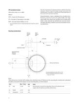
Note: The customization of codewheel method is valid from theoretical standpoint. However Avago Technologies strongly recommends a full characterization to be done to determine the actual performance of the encoder with customized codewheel. CPR calculation formula: CPR = (LPI x 25.4) x 2 x π x ROP Where: CPR = Counts Per Revolutions LPI = Encoder LPI provided in the table ROP = Encoder Optical Radius in mm * Recommended maximum Codewheel diameter should not exceed 30mm Characterization means validating the encoding performance (consist of cycle error, pulse width error, logic state width...
Open the catalog to page 7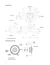
Package Dimension Optical Center Axis 17.80 21.60 R15.50 1.60 4.40 Optical Center Axis 2.69 Optical Center Axis 1.27 Front View Side View 21.60 TYPICAL DIMENSIONS IN MILLIMETERS Codewheel Mechanical Drawing 5.95 (0.234) MAX. 1.80 (0.071) MOUNTING BOSS SETSCREW INDEX PULSE REFERENCE MARKER INDEX PULSE POSITION
Open the catalog to page 8
For product information and a complete list of distributors, please go to our web site: www.avagotech.com Avago, Avago Technologies, and the A logo are trademarks of Avago Technologies in the United States and other countries. «• Data subject to change. Copyright © 2005-2009 Avago Technologies. All rights reserved. Obsoletes 5989-3823EN f
Open the catalog to page 9All Avago Technologies catalogs and technical brochures
-
AFCD-V84LP
1 Pages
-
BCM4778
2 Pages
-
AFBR-57H5MZ
29 Pages
-
ASMB-UTF0-0D20B
12 Pages
-
ASMT-YTD7-0AA02
15 Pages
-
ASMT-YTC7-0AA02
15 Pages
-
ASMT-RF45-AN002
8 Pages
-
Optical Sensor
64 Pages
Archived catalogs
-
WLAN Low-Noise Amplifier
10 Pages
-
Optoisolation Products
58 Pages
-
125 Megabaud Versatile Link
12 Pages
-
LED Solutions
96 Pages


