 Website:
AUTOMATIC SYSTEMS
Group: Automatic Systems
Catalog excerpts

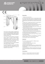
345182 7 6 Description > 1. Stainless steel sheet frame.2. Front and rear sections made of stainless steel locked from inside. These sections can not be opened before upper cover removal. They are designed to incorporate user control equipment such as card reader, coin acceptor, proximity reader, etc.3. Upper cover in stainless steel with lock, to ease access to the turnstile mechanism and to open the columns.4. Tripod turnstile mechanism with solid steel arms and capstan on ball bearings, protected by a black PVC hub cover. Electromagnetically operating locking bolts mounted on self lubricating bearings to lock arms. Hydraulic adjustable pressure movement shock absorber ensuring silent smooth operation and progressive slowing down of the arm rotation even when used with force. Reversed rotation prevented by the anti pass back device. 5. Stainless steel arms with locking device preventing the arm from being removed without appropriate tools.6. Programmable electronic control logic TR6 (see relevant Technical Data Sheet)7Each gate is designed to accomodate an orientation pictogram display in one or both directions (optional)8.Floor fixing by means of expansible plugs. The TR 491 tripod turnstile is designed for an economic and dissuasive access control and can incorporate access control devices such as: card readers, coin/token acceptors, ticketing systems, etc ...The TR 491 turnstile includes an anti-panic device, which, in case of power failure, automatically unlocks the arm, which instantaneously drops. The access corridor is then fully free of any obstruction, thus allowing uninterrupted safe passage.The repositioning of the arm is done manually when power supply is restored. Its mechanical design is strong and reliable allowing 7 different configurations to suit all architectural requirements in terms of pedestrian access control. Operation > The TR 491 turnstile can operate in 3 different modes. 1. Access permanently free2. Access permanently mechanically locked5. Electrically controlled access.All above operation modes include the arm dropping function providing free and unobstructed safe passage for users in case of power failure.The mode of operation is defined by specifying the code number above for both directions, which corresponds to the operation selected: Conventions: > Direction A = housing at right hand side of the walkwayDirection B = housing at left hand side of the walkway
Open the catalog to page 1All AUTOMATIC SYSTEMS catalogs and technical brochures
-
FIRSTLANE
16 Pages
-
BL4X
4 Pages
-
SmartLane
16 Pages
-
INTERLOCK_2018
4 Pages
-
BLG brochure
2 Pages
-
BL 15
2 Pages
-
RB brochure
4 Pages
-
TollPlus 262 - Toll Barrier
4 Pages
-
ParkPlus brochure
4 Pages
-
TollPlus 261 - Toll Barrier
4 Pages
-
BL 12 - Toll Barrier
2 Pages
-
PNG
4 Pages
-
PMD 335
2 Pages
Archived catalogs
-
SlimLane_2020
16 Pages
-
ClearLock_2015
4 Pages
-
BL 4x brochure
4 Pages
-
SlimLane_2013
4 Pages
-
SmartLane
4 Pages
-
INTERLOCK_2012
4 Pages
-
CLEARLOCK_2012
4 Pages
-
TBV/PPV
2 Pages
-
retractable bollard RB 60/80
2 Pages
-
gate PNG 380
2 Pages
-
revolving door TRS 360
2 Pages
-
swing gate PMD 337
2 Pages


