- Company
- Products
- Catalogs
- News & Trends
- Exhibitions
Datasheet INV
1 /3Pages

Datasheet INV
1 /3Pages
Catalog excerpts

Sinusoid wave PWM digital inverter 1Ph or 3Ph Main features: - - - - - - - The AUNILEC INV series offers a range of one- and threephase inverters with IGBT power conversion bridge. The system has been designed to continuously supply extra-low harmonics AC current to critical loads. The integrated static switch can automatically perform quick switching operations on the DC line, in case of black-out only, to substantially increase the global efficiency; it can also perform an ON-LINE conversion, in which the wave form is always generated by the inverter, thus ensuring a stable, undistorted waveform. In this case the load is switched to the emergency line only in case of inverter failure. The fast control system and the high-frequency PWM technology allow to connect the inverter to non-linear loads with a very low waveform distortion. The graphical display allows to show an easy to understand one-line diagram displaying the current status of the inverter and of the static switch, thus providing an accurate overview of the alarms and measurements. Clean and stable output AC with THD <2%. Redundant fan system with temperature and air flow control. By-pass static switch. Line Interactive mode efficiency >98%; on-line mode: >93%. Manual by-pass switch, allowing to perform maintenance operations without disconnecting the load. Possibility to supply a non-linear load with minimum distortion thanks to the high-frequency IGBT technology. Fuse protection on both the inverter and the emergency line, with burnt fuse identification and automatic insertion on the functional branch. Wide range of input voltages. Digital microprocessor control (DSP + PLD). Full optical isolation on all the logic and interface cards. Certified to operate in the harshest environment conditions. Overload capacity: 150% for 1 minute, 110% for 2 hours. Shortcircuit-proof architecture. Modbus communication interface through RS232 or RS485 port. Ethernet connectivity. Parallel and hot stand-by systems To ensure the power supply continuity, AUNILEC adopts two solutions: HOT STAND-BY and N+1 redundancy. The hot stand-by mode uses two identical inverters and powers the load with one of them, while the other is active and synchronised with the mains, ready to intervene in no time should the first machine fail. The N+1 redundancy solution uses multiple inverters connected in parallel, always on and running, dividing the current load among them; the whole system is designed to ensure load powering even in case of inverter failure. Should the failure involve more than one inverter, the load is switched anyway to the emergency line without any power supply interruption.
Open the catalog to page 1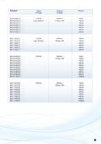
Input voltage Output voltage
Open the catalog to page 2
OTHER TECHNICAL CHARACTERISTICS Output distortion <2% (VFI-SS-III class according to IEC/CEI EN 62040) Dynamic stability -8%/+13% restore to ±1 % in 80ms Contacts in terminal box Voltage-free contacts Remote controls ON/OFF switch, Man. charge, Probe temp. Communication Modbus protocol via RS485 DB9 serial port; TCP/IP Cooling Forced Temperature -5/+40°C, 93% humidity (without condensation) Noise level 50 to 60dB (depending on sizes) Metal frame thickness 2.5mm Metal door thickness 1.5mm Frame Galvanised steel Protection degree with closed door IP30 Protection degree with open door IP20 Cable...
Open the catalog to page 3All AUNILEC catalogs and technical brochures
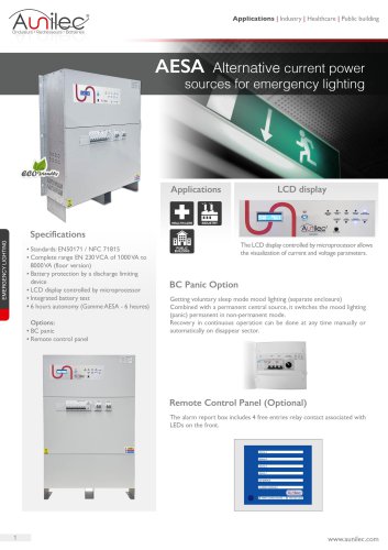 AESA Wall-Mounted And Floor
2 Pages
 Datasheet MULTI PLUS
5 Pages
 Datasheet IRIS+
2 Pages
 Datasheet IRIS-RT 6-10
2 Pages
 Datasheet IRIS-LFP 1-3
2 Pages
 Datasheet IRIS-LFP 6-10
4 Pages
 Datasheet IRIS+L
2 Pages
 Datasheet HELIOS TH
4 Pages
 Datasheet AUPUS HE 5U
5 Pages
 DAtasheet AUPUS HE Cabinet
6 Pages
 Datasheet AUPUS-OC0864
5 Pages
 Datasheet AUPUS WRS
4 Pages
 Datasheet VEGA HE
4 Pages
 Datasheet Multi Plus News
10 Pages
 Datasheet HELIOS MPW
8 Pages
 Datasheet MHE AUPUS C
4 Pages
 Datasheet AESB-R
2 Pages
 Aunilec Datasheet AESB EN
2 Pages
 ARES RT 1000-3000VA
2 Pages
 ARES 1000-3000VA
2 Pages
 EPC D 600/800VA
2 Pages
 Aunilec ARES
2 Pages
 Power solutions catalogue
48 Pages
 after-sales service
6 Pages
 Aunilec MLTDSP datasheet EN
2 Pages
 After-sales service Aunilec
6 Pages
 Inverters AUPUS EIM
3 Pages
 Controllers VIDI AUPUS C
4 Pages
 AESATM/TT 10-80kVA
3 Pages
 CRFw 12Vcc, 24Vcc and 48Vcc
2 Pages
 INV 48V/300VA
1 Page
 Active power filter 400V
2 Pages
 Aunilec Battery analyzer
1 Page
 Aunilec Batteries
1 Page
 Aunilec DSP Power Solutions
4 Pages
 Aunilec VEGA
6 Pages
 Aunilec ARFDin
2 Pages
 Power factor correction B50
4 Pages
 Power factor correction B35
4 Pages
 Power factor correction B25
4 Pages
 Série EOS|D 650-2200VA
2 Pages
 Série EOS 650-2200VA
2 Pages
 NET600 600VA
2 Pages
 Datasheet DSP
4 Pages
 Datasheet MultiPlus
4 Pages
 Datasheet OP 5_10kVA
2 Pages
 Datasheet OP 1_3kVA
2 Pages
 Datasheet CRFw
2 Pages
 Datasheet ARFDin
2 Pages
 Datasheet helios modular
4 Pages
 Datasheet Helios 20S
2 Pages
 Datasheet Helios STR
2 Pages
 Datasheet MPTR
2 Pages
 Datasheet RDC
4 Pages


Archived catalogs
 Aunilec battery 12 years EN
2 Pages
 Lead Carbon battery
2 Pages
 Live&smart MLTDSP EN
2 Pages
 Datasheet RCRFn
2 Pages
 Datasheet AESA
2 Pages
 Protection and energy saving
61 Pages
 Aunilec MLTDSP Brochure EN
4 Pages
 Live&smart AUNISOL EN
2 Pages
 Carbon battery
3 Pages
 Charger CRFD
2 Pages
 Power solutions
48 Pages
 Gel batteries
2 Pages
 Datasheet ARES Rack
2 Pages
 HELIOS MPW
7 Pages
 UPS catalogue 2019-2020
60 Pages
 AUPUS HE Cabinet
6 Pages
 Datasheet charger AUPUS WRS
4 Pages
 Datasheet Aunisol 3-5-10
4 Pages
 Datasheet Aunisol 1-20
2 Pages
 Catalogue Power solutions
48 Pages


- DC power supply
- AC/DC power supply
- Transformer
- Monitoring analyzer
- Dry transformer
- CE power supply
- Single-output power supply
- Battery charger
- Power supply with overload protection
- Compact power supply
- Encapsulated transformer
- DIN rail power supply
- Power transformer
- Electronic filter
- Lithium battery
- Variable-output power supply
- 12 V battery
- Isolation transformer
- Single-phase power supply