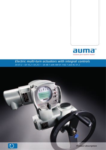
Electric multi-turn actuators
1 /40Pages

Electric multi-turn actuators
1 /40Pages
Catalog excerpts
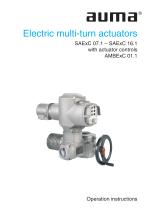
Electric multi-turn actuators SAExC 07.1 – SAExC 16.1 with actuator controls AMBExC 01.1 Operation instructions
Open the catalog to page 1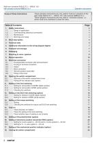
Multi-turn actuators SAExC 07.1 – SAExC 16.1 with actuator controls AMBExC 01.1 Scope of these instructions: Operation instructions These operation instructions are only valid for multi-turn actuators of the type range SAExC 07.1 – SAExC 16.1 with controls AMBExC 01.1. These operation instructions are only valid for ”clockwise closing”, i.e. driven shaft turns clockwise to close the valve. 1. Safety instructions 1.1 Range of application 1.2 Commissioning (electrical connection) 1.3 Maintenance 1.4 Warnings and notes Short description Technical data Additional information to the wiring diagram...
Open the catalog to page 2
Operation instructions Multi-turn actuators SAExC 07.1 – SAExC 16.1 with actuator controls AMBExC 01.1 19. Controls AUMA MATIC BASIC ExC 19.1 Removal of the local controls 19.2 Setting the type of seating in the end position CLOSED 19.3 Push-to-run operation or self-retaining in selector switch position LOCAL 19.4 Push-to-run operation or self-retaining in selector switch position REMOTE 19.5 Fitting the local controls 19.6 Settings on relay board for potential-free feedback (option) Spare parts list multi-turn actuator SAExC 07.1 – SAExC 16.1 Spare parts list controls AMBExC with plug/socket...
Open the catalog to page 3
Multi-turn actuators SAExC 07.1 – SAExC 16.1 with actuator controls AMBExC 01.1 Operation instructions Safety instructions AUMA actuators are designed for the operation of industrial valves, e.g. globe valves, gate valves, butterfly valves and ball valves. For other applications, please consult us. The manufacturer is not liable for any possible damage resulting from use in other than the designated applications. Such risk lies entirely with the user. Observance of these operation instructions is considered as part of the controls'/actuator's designated use. Commissioning (electrical connection)...
Open the catalog to page 4
Multi-turn actuators SAExC 07.1 – SAExC 16.1 with actuator controls AMBExC 01.1 Operation instructions Technical data Table 1: Technical data SAExC 07.1 – SAExC 16.1 Features and functions Explosion protection Protection types EC type examination certificate Type of duty 1) Motors Insulation class Motor protection Self-locking Limit switching Torque switching Position feedback signal, analogue (options) Mechanical position indicator (option) Running indication Heater in switch compartment Manual operation Electrical connection to the controls Threads for cable glands Terminal plan Output drive...
Open the catalog to page 5
Multi-turn actuators SAExC 07.1 – SAExC 16.1 with actuator controls AMBExC 01.1 Standard colour Ambient temperature3) Vibration resistance4) according to EN 60068-2-6 Lifetime Silver-grey (similar to RAL 7037) Other colours are possible on request – 20 °C to + 40 °C – 40 °C to + 40 °C (low temperature) – 50 °C to + 40 °C (extreme low temperature) 1 g, from 10 Hz to 200 Hz Standard: Option: Standard: Options: Type SAExC 07.1 – SAExC 10.1 SAExC 14.1 – SAExC 16.1 Other information EC directives Reference documents Operation instructions Operating cycles (OPEN-CLOSED-OPEN) with 30 turns per stroke...
Open the catalog to page 6
Multi-turn actuators SAExC 07.1 – SAExC 16.1 with actuator controls AMBExC 01.1 Operation instructions Additional information to the wiring diagram legend Information A: Change-over switch S9 for changing the type of seating (see subclause 19.2, page 24). Self-retaining in local operation can be cancelled by cutting the jumper B3 (see subclause 19.3, page 25). Jumper for operation mode REMOTE (see subclause 19.4, page 25). The control voltage is 115 V or 230 V AC (according to order) and must only be switched via potential-free contacts. End position signal: 115 V or 230 V AC, max. 2.5 W. Instead...
Open the catalog to page 7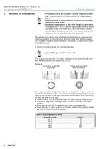
Multi-turn actuators SAExC 07.1 – SAExC 16.1 with actuator controls AMBExC 01.1 Operation instructions Prior to mounting the actuator must be checked for damage. Damaged parts must be replaced by original spare parts. After mounting to valve/ gearbox, touch up any possible damage to paint finish. Increased temperatures at the valve flange or valve stem: If temperatures > 40 °C are to be expected at the valve mounting flange or the valve stem (e.g. due to hot media), please consult AUMA. Temperatures > 40 °C are not considered with regards to the non-electrical explosion protection. Mounting is...
Open the catalog to page 8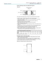
Multi-turn actuators SAExC 07.1 – SAExC 16.1 with actuator controls AMBExC 01.1 Operation instructions Finish machining of stem nut (output drive type A): Figure B-1 Output drive type A Stem nut The output drive flange does not have to be removed from the actuator. Remove spigot ring (80.2, figure B-1) from mounting flange. Take off stem nut (80.3) together with thrust bearing (80.01) and thrust bearing races (80.02). Remove thrust bearing and thrust bearing races from stem nut. Drill and bore stem nut and cut thread. When fixing in the chuck, make sure stem nut runs true! Clean the machined...
Open the catalog to page 9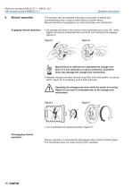
Multi-turn actuators SAExC 07.1 – SAExC 16.1 with actuator controls AMBExC 01.1 Manual operation Engaging manual operation: Operation instructions The actuator may be operated manually for purposes of setting and commissioning, and in case of motor failure or power failure. Manual operation is engaged by an internal change-over mechanism. Lift change-over lever in the centre of the handwheel up to max. 85°, while slightly turning the handwheel back and forth until manual drive engages (figure C). Manual force is sufficient for operating the change-over lever. It is not necessary to use an extension....
Open the catalog to page 10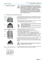
Multi-turn actuators SAExC 07.1 – SAExC 16.1 with actuator controls AMBExC 01.1 Operation instructions Electrical connection Ex-plug/socket connector with terminal board When working in potentially explosive areas, observe the European Standards EN 60079-14 “Electrical Installations in Hazardous Areas” and EN 60079-17 “Inspection and Maintenance of Electrical Installations in Hazardous Areas”. Work on the electrical system or equipment must only be carried out by a skilled electrician himself or by specially instructed personnel under the control and supervision of such an electrician and in...
Open the catalog to page 11All AUMA catalogs and technical brochures
 ELECTRIC ACTUATORS
6 Pages
 Multi-turn actuators
92 Pages
 SAEx 07.2
1 Page
 AUMA Cloud + AUMA Assistant App
14 Pages
 FUNCTIONAL SAFETY – SIL
28 Pages
 Service Worldwide
8 Pages
 SIMA² Master Station
6 Pages
 AUMA Support App
4 Pages
 electric actuators
56 Pages
 FUNCTIONAL SAFETY SIL
28 Pages
 Service world wide
12 Pages
 Explosions proof actuators
24 Pages
 The Actuator Specialist
32 Pages


Archived catalogs
 Electric multi-turn actuators
24 Pages
 Electric multi-turn actuators
28 Pages
 Master station SIMA
4 Pages
 Multi-turn gearbox GHT 360.1
4 Pages
 Electric part-turn actuators
4 Pages
 Service device PV 788 B
4 Pages
 Test bench PV 1405
24 Pages


- Planetary gearbox
- Coaxial gearhead
- Right angle gearhead
- Compact gearhead
- Gear train gear reducer
- AUMA hollow-shaft gear reducer
- AUMA valve actuator
- Shaft gearhead
- AUMA rotary valve actuator
- Low-noise gearhead
- High-torque gearhead
- Bevel gearhead
- AUMA electric valve actuator
- Parallel-shaft gearhead
- Drive gear reducer
- Compact valve actuator
- Linear valve actuator
- Aluminum valve actuator
- Spur gearhead
- AUMA modulating valve actuator