Electric multi-turn actuators
1 /24Pages

Electric multi-turn actuators
1 /24Pages
Catalog excerpts

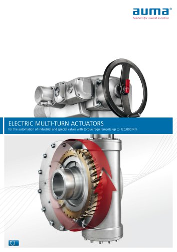
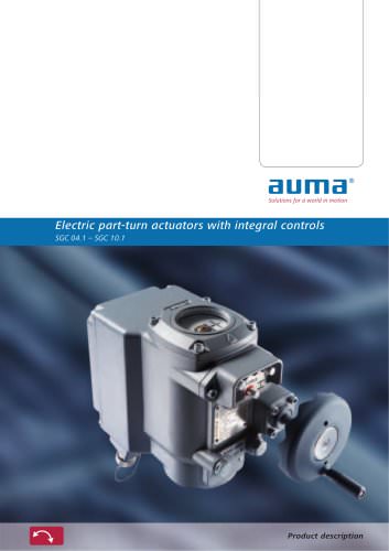
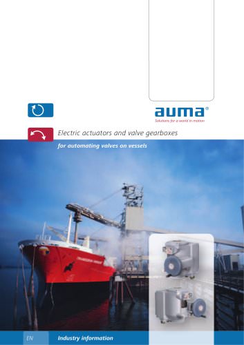
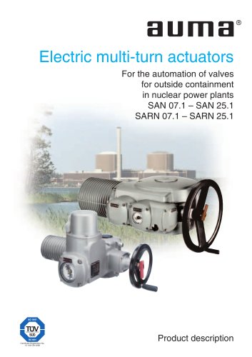
Electric multi-turn actuators For the automation of valves for outside containment in nuclear power plants SAN 07.1 – SAN 25.1 SARN 07.1 – SARN 25.1 Certificate Registration No. 12 100/104 4269 Product description
Open the catalog to page 1
Electric actuators are among the most important components of the safety system of a nuclear power plant. This means that the actuators have to operate the valve correctly under defined conditions, e.g. to remain safely operable even under For more than 20 years AUMA has manufactured electric actuators for use in nuclear power plants. During this time AUMA has acquired a know-how in this field that can hardly leading electric actuator manufactur- AUMA has two multi-turn actuator ranges SAN/ SARN and SAI that are qualified for the use in nuclear power approved for the use 'inside Contain- ment',...
Open the catalog to page 2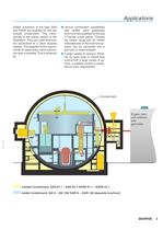
Applications AUMA actutators of the type SAN and SARN are qualified for the use outside containment. This corresponds to the yellow section in the illustration. They are used wherever the automation of a valve requires rotation. The adaption to the requirements of nearly every valve automation task is possible. This is achieved by: ■ various combination possibilities with AUMA valve gearboxes which are also qualified for the use in nuclear power plants. Thereby the torque range can be further extended and/ or the multi-turn actuator can be converted into a part-turn or linear actuator ■ a large...
Open the catalog to page 3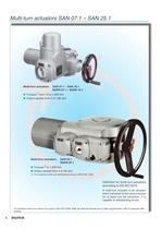
Multi-turn actuators SAN 07.1 – SAN 25.1 Multi-turn actuators SAN 07.1 – SAN 16.1 SARN 07.1 – SARN 16.1 ■ Torques1) from 10 to 1,000 Nm ■ Output speeds from 4 to 180 rpm Multi-turn actuators SAN 25.1 SARN 25.1 ■ Torques1) to 1,600 Nm ■ Output speeds from 4 to 90 rpm 1) For actuators which are certified according to IEEE 382-1996. Definition for multi-turn actuators according to EN ISO 5210 A multi-turn actuator is an actuator which transmits to the valve a torque for at least one full revolution. It is capable of withstanding thrust. For actuators which are used in the scope of the KTA 3504-1988,...
Open the catalog to page 4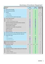
Summary of functions/ Equipment Functions ● Standard ■ Option Open-close duty (SAN) Seating – Torque seating Equipment Overload protection against torque peaks Limit / torque switches – Tandem switches – Switches with gold-plated contacts DUO limit switching (intermediate position switches) Mechanical position indicator Remote position indicator Combinations with AUMA valve gearboxes 3-phase AC motor Motor protection Manual operation Electrical connection with AUMA plug/ socket connector Valve attachment according to ISO 5210 / DIN 3210 SARN 07.1 – 25.1 ● Description on page 6 ● ● ● ● ● ● ● ●...
Open the catalog to page 5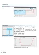
Functions Type designation A type code defines the various versions. SA N ‘R’ version for modulating duty Approved for outside Containment Size e.g. 07.1 Flange size e.g. F10 applicable for all versions only if applicable to define a version Open-close duty Input Actuator for open-close duty Valve The usual valve positions in open-close duty are the end positions OPEN and CLOSED. Upon receiving an appropriate command the actuator moves the valve to one of the two end positions or, if necessary, to a pre-defined intermediate position. Type of duty for multi-turn actuators for open-close duty (SAN)...
Open the catalog to page 6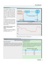
Functions Modulating duty The controlled variable in a modulating application is affected by many influences. A change of the reference input signal, pressure fluctuation in the pipeline and temperature variations influence the process in such a way that a frequent adjustment of the MOV is required. For sensitive modulating applications the starts may be in intervals of a few seconds. Input signal from process controller Feedback signal to process controller Valve position feedback Therefore high demands are placed on actuators for this duty. Mechanical components and the motor must be designed...
Open the catalog to page 7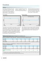
Functions Seating Depending on the design of the valve to be operated, end position switching either limit seating, i.e. by measuring the valve travel completed, or torque seating, i.e. after reaching a defined torque. For this purpose, the actuator is equipped with two independent measuring systems, i.e. limit switching and torque switching. Limit seating The type of seating has to be taken in account both when setting the actuator and in the actuator control. However, the processing of signals for the two types of seating differs. Torque seating Torque Speed Set tripping torque P Travel OPEN...
Open the catalog to page 8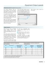
Equipment/ Output speeds Overload protection against torque peaks If excessive torque builds up in the valve in an intermediate position, e.g. due to a trapped object, the torque switching trips after reaching the set tripping torque. After the controls have processed the torque switch signal accordingly, the motor will be switched off. As a result, valve and actuator are protected from damage. If the limit switch signals are processed accordingly in the controls, you can distinguish between a normal torque switch tripping at the end positions and tripping in an interme- diate position (fault)...
Open the catalog to page 9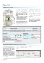
Equipment Limit and torque switches If the actuator is supplied with DUO limit switching (refer to page 10) two more limit switches for intermediate positions are available. With the help of the switches, the mechanically measured travel (i.e. number of turns) and torque are converted into usable signals for the actuator controls. The switches are integrated into the control unit which contains four switches in the basic version: To meet the high demands regarding reliability, AUMA uses specially developed high quality microswitches with a snap action mechanism. ■ one limit switch each for the...
Open the catalog to page 10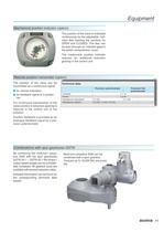
Equipment Mechanical position indicator (option) The position of the valve is indicated continuously by the adjustable indicator disc bearing the symbols for OPEN and CLOSED. The disc can be seen through an indicator glass in the switch compartment cover. The mechanical position indicator requires an additional reduction gearing in the control unit. Remote position transmitter (option) The position of the valve can be transmitted as a continuous signal: ■ for remote indication ■ as feedback signal to a positioner For continuous transmission of the valve position a reduction gearing is required...
Open the catalog to page 11All AUMA catalogs and technical brochures
 ELECTRIC ACTUATORS
6 Pages
 Multi-turn actuators
92 Pages
 Electric multi-turn actuators
40 Pages
 SAEx 07.2
1 Page
 AUMA Cloud + AUMA Assistant App
14 Pages
 FUNCTIONAL SAFETY – SIL
28 Pages
 Service Worldwide
8 Pages
 SIMA² Master Station
6 Pages
 AUMA Support App
4 Pages
 electric actuators
56 Pages
 FUNCTIONAL SAFETY SIL
28 Pages
 Service world wide
12 Pages
 Explosions proof actuators
24 Pages
 The Actuator Specialist
32 Pages


Archived catalogs
 Electric multi-turn actuators
28 Pages
 Master station SIMA
4 Pages
 Multi-turn gearbox GHT 360.1
4 Pages
 Electric part-turn actuators
4 Pages
 Service device PV 788 B
4 Pages
 Test bench PV 1405
24 Pages


- Planetary gearbox
- Coaxial gearhead
- Right angle gearhead
- Compact gearhead
- Gear train gear reducer
- AUMA hollow-shaft gear reducer
- AUMA valve actuator
- Shaft gearhead
- AUMA rotary valve actuator
- Low-noise gearhead
- High-torque gearhead
- Bevel gearhead
- AUMA electric valve actuator
- Parallel-shaft gearhead
- Drive gear reducer
- Compact valve actuator
- Linear valve actuator
- Aluminum valve actuator
- Spur gearhead
- AUMA modulating valve actuator