- Products
- Catalogs
- News & Trends
- Exhibitions
Servo proportional valves

Servo proportional valves
Catalog excerpts

DLHZO =size 06 Synthetic fluids DLKZOR =size 10 WG =water-glycol PE =phosphate ester T = with position transducer TE = as T plus integral electronics Series number TES = as T plus integral digital electronics > Hydraulic options, see section : B =solenoid, integral electronics andposition transducer at side of port A > Communication interfaces (only for TES) PS = RS232 serial Y =external drain BC = CANbus BP = PROFIBUS-DP Electronics options, for -TE executionsee section : F =fault signal > Valve size , see section = ISO 4401 size 06 1 = ISO 4401 size 10 I =current reference input and monitor (4շ20 mA) Q =enable signal Valve configuration, see section Z =enable, fault and monitor signals 4 =2 external position, spring offset, fail safe 6 =2 external position, spring offset Electronics options, for -TES executionsee section : Spool type (regulating characteristics) =zero overlapping I =current reference input and monitor (420mA) Z = double power supply, enable fault andmonitor L = linear; D = differential-linear (as L , but with P-A = Q, P-B = Q/2) > (1) Special options for -TES execution DT = as D , but with non linear regulation > (1) see section : T = not linear regulation > (1) SF = additional closed loop force control, V = progressive with two remote pressure transducers SL = additional closed loop force control 0, 1, 3, 5, 7 = spool size, see section with one remote load cell SP = additional closed loop pressurecontrol with one remote pressure transducer > C = current feedback interface for transdu-cer(s) Fail safe configuration (de-energized solenoid): only for options /SF, /SL, /SP > 1 = A, B, P, T with positive overlapping (20% of spool stroke) 3 =P positive overlapping (20% of spool stroke); A, B, T negative > (1) Spool type D, DT and T are available only for valve configuration with fail safe position DLHZO-*-040 and DLKZOR-*-140 > For power supply and communication connector see section > 16 and 18 F180 >
Open the catalog to page 1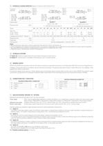
3HYDRAULIC CHARACTERISTICS (based on mineral oil ISO VG 46 at 50 C) *60-L*1/B*60-V*1/Baaab zero point displacement < 1% at Valve modelPressure limits [bar] DLHZO-T* DLKZOR-T* ports P, A, B = 350; T = 160 (250 with external drain /Y) ports P, A, B = 315; T = 160 (250 with external drain /Y) SpoolLeakage [cm L0 L1V1L3V3L5T5L7T7V7D7DT7L3L7T7V7D7DT7 Max flow[l/min]at ТȆ p = 30 barat 4,57589141320182826402613402040606510065緷3310050 碈 p = 70 bar2,54 10 15 > 3 /min] at P = 100 bar > (1) <100<100<150<200<200 <200<300<500 0,1% <200 <900<200 <700 <1000<1500 <400 0,1% Hydraulicsymbols*60-L*1*60-V*1bb <400...
Open the catalog to page 2
8ANALOG INTEGRAL DRIVERS -TE - MAIN FUNCTIONS AND ELECTRONIC CONNECTIONS MAIN CONNECTOR REGULATIONS AND LED > 7 PIN - STANDARD (remove the rear cover) BIASSCALEDIAGNOSTIC B2B1S2S1 (driver view)(driver view) 12 PIN - OPTION /Z LED B1:B2:S1:S2: bias adjust not workingpositive scale adjustnegative scale adjust LED: OFF normal working; ON fault presence 8.1ELECTRONIC CONNECTIONS - 7 & 12 PIN MAIN CONNECTORS Standard7pin /Z option12pin SIGNAL TECHNICAL SPECIFICATIONS NOTES A 1 V+ Power supply 24 V > DC for solenoid power stage and driver logic Input - power supplyGnd - power supply B 2 V0 Power supply...
Open the catalog to page 3
13DIAGRAMS (based on mineral oil ISO VG 46 at 50 C) 13.1Regulation diagrams1 12 =Linear spools L 2 =Differential - linear spool D7 > Nominal flow [%] Nominal flow [%] Reference signal [Volt]Reference signal [Volt] 3 = Differential non linear spool DT7 4 = Non linear spool T5 (only for DLHZO) 3 Note 4 T5 and T7 spool types are specific for finelow flow control in the range form 0 to 40% (T5) and 0 to 60% (T7) of max spool stroke. The non linear characteristics of the spool is compensated by the electronic driver, so thefinal valve regulation is resulting linearrespect the reference signal (dotted...
Open the catalog to page 5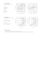
13.2Flow / ∆ p diagrams Stated at 100% of spool strokeDLHZO: 1 = spool L7, T7 2 = spool L5, T5 3 = spool L3 4 = spool L1DLKZOR: > Flow rate [l/min] Flow rate [l/min] 5 = spool L7, T7 6 = spool L3 Valve pressure drop ∆ p [bar] Valve pressure drop ∆ p [bar] 13.3Bode diagrams Stated at nominal hydraulic conditionsDLHZO: 1 = 100% nominal stroke 2 = ѱ 5% nominal strokeDLKZOR: 12123434 561234 13.4Dynamic response > Phase [degree]Amplitude ratio [dB] Phase [degree] 3 = 100% nominal stroke > Amplitude ratio [dB] 4 = ѱ 5% nominal stroke Frequency [Hz] Frequency [Hz] The response times in section have...
Open the catalog to page 6All ATOS catalogs and technical brochures
 Hydraulic filters
8 Pages
 Safety valves
11 Pages
 Technical leaflets TE
16 Pages
 Technical leaflets TC
16 Pages
 Technical leaflets TX
6 Pages
 Technical leaflets TZ
16 Pages
 PFE-31, PFE-41, PFE-51
4 Pages
 Hand pumps type PM
2 Pages
 Double vane pumps
4 Pages
 PVPC pumps
6 Pages
 PFEO-41 and PFEDO-43
4 Pages


- Control valve
- Cylinder
- Liquid filter
- Flap valve
- Check valve
- Directional control valve
- Double-acting cylinder
- Hydraulic pump
- Filter with cartridge
- Hydraulic cylinder
- Piston actuator valve
- Oil valve
- Hydraulic valve
- 2-channel valve
- Hydraulic directional control valve
- Flow control valve
- Pack unit
- Hydraulic piston pump
- Pneumatic directional control valve