

Safety valves

Safety valves
Catalog excerpts

Safety valves direct, pilot operated and cartridge execution with inductive position or proximity switches conforming to Machine Directive 2006/42/CE Safety valves are designed to fulfil the safety criteria imposed to machine manufacturers by the European Machine Directive. They are CE marked and certified by TÜV, in accordance with the technical safety requirements provided in the Machine Directive 2006/42/CE but not included in the safety components of annex IV. In addition to the normal hydraulic function they are equipped with inductive or proximity switches; with the on/off switch indicates the position of the spool/poppet of the valve. These valves are normally used to cut off the hydraulic power line in case of emergency condition, thus avoiding dangerous movements of the machines actuators. By checking the switch status, corresponding to “open” or “intercepted” hydraulic line, the machine controller can perform the safety function. Two versions are available: - FI inductive proximity switch ቢ; - FV inductive position switch (double contacts) ባ; see section 14 for technical characteristics. Safety valves are available in direct, piloted and cartridge executions, with same hydraulic and electric characteristics of standard products from which they are derived. Typical application is on vertical and horizontal presses to shut off the fluid energy to one or more actuators as a consequence of the opening of the machine “gate” or as a consequence of an “emergency stop” command. For details about the applicable EN standards, see www.atos.com, catalog on line, section P, table P004. RANGE OF VALVE’S MODELS DC solenoids Valve code Switch type direct operated solenoid valves, on-off, single solenoid direct operated solenoid valves, on-off, double solenoid direct operated solenoid valves, on-off, single solenoid direct operated solenoid valves, on-off, double solenoid direct operated solenoid valves, on-off, single solenoid direct operated solenoid valves, on-off, double solenoid piloted operated solenoid valves, on-off, with DHE or DHI pilot intermediate elements with cartridge, to be coupled with a specific cover on-off cartridges on-off active cartridges
Open the catalog to page 1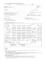
MODEL CODE OF DIRECT OPERATED SAFETY SOLENOID VALVES /* Seals material: omit for NBR (mineral oil & water glycol) PE = FPM Type of solenoid valve DHI, DHE = direct, size 06 (see tab. E010, E015) DKE = direct, size 10 (see tab E025) Series number Size ISO 4401 0 = size 06 (DH*) 1 = size 10 (DK*) Voltage code, see section 15 Valve configuration, see section ݙ 61 = single solenoid, central plus external position, spring centered 63 = single solenoid, 2 external positions, spring offset 67 = single solenoid, external plus central position, spring offset 71 = double solenoid, 3 positions, spring...
Open the catalog to page 2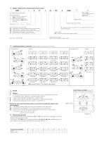
MODEL CODE of pilot operated safety solenoid valves /* Seals material: omit for NBR (mineral oil & water glycol) PE = FPM Two stage directional control valve Solenoid pilot valve: I = DHI for AC and DC supply with CURUS certified solenoids E = DHE for AC and DC supply, high performances with CURUS certified solenoids Valve size: 1 = 10 Series number Voltage code, see section 15 Valve configuration, see section :ݜ 61 = single solenoid, center plus external position, spring centered 63 = single solenoid, 2 external positions, spring offset 67 = single solenoid, center plus external position,...
Open the catalog to page 3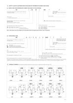
SAFETY VALVES IN CARTRIDGE EXECUTION (MADE BY INTERMEDIATE ELEMENT AND COVER) 8.1 MODEL CODE FOR INTERMEDIATE ELEMENT INCLUSIVE OF THE CARTRIDGE /* Seals material: omit for NBR (mineral oil & water glycol) PE = FPM Intermediate element (with poppet position detector) including the cartridge Series number Type of switch: I = inductive proximity switch Size (ISO 7368), the same of the cover - see section 24 16; 25; 32; 40; 50 Other dimensions available on request /NC = closed contact with poppet in resting position Spring cracking pressure: Type of poppet, see tab. H030 for Q/Δp diagrams 42 = With...
Open the catalog to page 4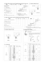
MODEL CODE OF SAFETY VALVES IN CARTRIDGE EXECUTION (INTEGRAL DESIGN COVER) Safety cartridge valve according to ISO 7368 Only for LIDAH X = Voltage code see section 15 poppet type: 43 = with damping nose, area ratio 1:2 (size 16 and 25) 1:1,6 (size 32,40 and 50) Only for LIDAH without solenoid connectors to be ordered separately (see tab. K500) spring cracking pressure: 1 = 0,6 bar 3 = 3 bar 6 = 5,5 bar LIDAH-**43/FV Pilot solenoid valve -I = DHI for AC and DC supply, with CURUS certified solenoids -E = DHE for AC and DC supply, high performances, with CURUS certified solenoids Type of switch:...
Open the catalog to page 5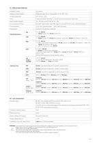
MAIN CHARACTERISTICS Installation position Subplate surface finishing Roughness index Ra 0,4 - flatness ratio 0,01/100 (ISO 1101) Ambient temperature Recommended viscosity Fluid contamination class ISO 4406 class 21/19/16 NAS 1638 class 10, in line filters of 25 μm (β10 >75 recommended) _ Fluid temperature Flow direction As shown in the symbols of tables ݙ P, A, B = 350 bar T = 100 bar (version /FI); 210 bar (DC solenoid - version /FV); 160 bar (AC solenoid - version /FV) P, A, B = 350 bar T = (with Y port not connected to tank) 100 bar (version /FI); 210 bar (DC solenoid - version /FV); 120...
Open the catalog to page 6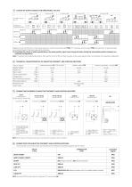
STATUS OF OUTPUT SIGNAL FOR DIRECTIONAL VALVES Configuration 67 HYDRAULIC CONFIGURATION high level low level high level low level high level Diagrams show the behaviour of the output signal for inductive switches type FI/NO. For inductive switches type FI/NC the behaviour is opposite (high level signal instead of low level signal and viceversa) (1) According the criteria of safety specifications, the spool position signal must change its status during the intermediate position between two hydraulic configurations. Note: FV versions can be electrically wired by the customer as NO or NC and then...
Open the catalog to page 7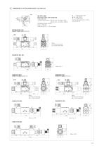
[2lj DIMENSIONS for DH* SOLENOID SAFETY VALVES [mm] Fastening bolts: 4 socket head screws: M5X50 class 12.9 (DHI, DHU)
Open the catalog to page 8All ATOS catalogs and technical brochures
 Hydraulic filters
8 Pages
 Technical leaflets TE
16 Pages
 Technical leaflets TC
16 Pages
 Technical leaflets TX
6 Pages
 Technical leaflets TZ
16 Pages
 PFE-31, PFE-41, PFE-51
4 Pages
 Hand pumps type PM
2 Pages
 Double vane pumps
4 Pages
 PVPC pumps
6 Pages
 PFEO-41 and PFEDO-43
4 Pages


Archived catalogs
 Servo proportional valves
8 Pages
- Cylinder
- Liquid filter
- Flap valve
- Check valve
- Directional control valve
- Hydraulic pump
- Double-acting cylinder
- Filter with cartridge
- Hydraulic cylinder
- Lift valve
- Oil valve
- Hydraulic valve
- 2-channel valve
- Hydraulic directional control valve
- Flow control valve
- Hydraulic piston pump
- Pack unit
- Spool hydraulic directional control valve