- Products
- Catalogs
- News & Trends
- Exhibitions
PVPC pumps
1 /6Pages

PVPC pumps
1 /6Pages
Catalog excerpts
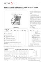
Proportional electrohydraulic controls for PVPC pumps pressure-flow alternate P/Q controls, analog or digital The variable displacement axial piston pumps type PVPC, can be supplied with advanced electrohydraulic proportional controls: • open loop pressure control; • load sensing flow control; • Open and closed loop P/Q controls; They allow to perform high dynamics and fine regulations, directly commanded from PLC or from the machine controller. They are available with separated driver or with integral electronics ቢ. New PES digital controllers, integrated to the pump, realize alternate closed loop controls of pressure, flow and max power limitation. The P/Q controls are also available with optional sequence module (LZQZR or PERS versions) that allow to operate the pump with minimum pressure in the circuit close to zero. Following communication interfaces are available for the digital PE(R)S execution, see section :ݟ • -PS: Serial • -BC: CANopen • -BP: PROFIBUS DP For technical characteristics and features of the PVPC pumps, see table A160. MODEL CODE Additional suffix for double pumps X2E = with a fixed displacement pump type PFE (see tab. A005) Series number Type of control (see section ݝand :)ݞ CZ = proportional pressure compensator LQZ = proportional flow control (load sensing) LZQZ = proportional pressure & flow control (load sensing) LZQZR = as LZQZ plus sequence module PES = closed loop integral digital P/Q controller PERS = as PES plus sequence module Options, for CZ, LQZ, LZQZ, LZQZR see sections :ݙ 18 = optional coil for low current drivers Electronics options for PES and PE(R)S see sections ݚand :ݝ I = current reference input and monitor output signals (4 ÷ 20 mA) C =current feedback input signal (4÷20 mA) for remote pressure transducer X =with integral pressure transducer (only for PERS) S =with two on-off inputs for multiple pressure PID selection (PS execution) or double power supply (BC and BP execution) Communication interface, only for PES and PERS versions PS = Serial BP = PROFIBUS DP BC = CANopen Size: 3 = for displacement 029 4 = for displacement 046 5 = for displacement 073 and 090 Max displacement: 029 = 29 cm3/rev /* Seals material: omit for NBR (mineral oil & water glycol) PE = FPM See notes in section ݘ Variable displacement axial piston pump Direction of rotation (viewed at the shaft end) D = clockwise S = counterclockwise Type of PFE (for double pumps), see tab. A005 Pressure setting (only for PERS): 200 = 200 bar 1) pumps with ISO 3019/2 mounting flange and shaft (option /M) are available on request OPERATING CHARACTERISTICS Pump model Displacement Max working pressure / Peak pressure [bar] Min/Max inlet pressure Max pressure on drain port Power consumption at 1450 rpm and at [kW] maximum pressure and displacement External load position Max torque on the first shaft Max permissible load on drive shaft Speed rating Fax = axial load Frad = radial load Notes: For speeds over 1800 rpm the inlet port must be under oil level with adequate pipes. Maximum pressure for all models with water glycol fluid is 160 bar, with option /PE is 190 bar. Max speed with options /PE and water glycol fluid is 2000/1900/1600/1500 rpm respectively for the four sizes. A170
Open the catalog to page 1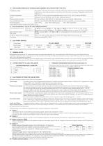
MAIN CHARACTERISTICS OF VARIABLE DISPLACEMENT AXIAL PISTON PUMP TYPE PVPC Installation position Ambient temperature Any position. The drain port must be on the top of the pump. Drain line must be separated and unrestricted to the reservoir and extended below the oil level as far from the inlet as possible. Suggested maximum line lenght is 3 m. from -20°C to +70°C for versions with separated electronics / from -20°C to + 60°C for versions PES/PERS Fluid Recommended viscosity Fluid contamination class Fluid temperature Power supply for pressure transducer (PES, PERS) Hydraulic oil as per DIN 51524...535;...
Open the catalog to page 2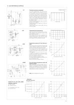
ELECTROHYDRAULIC CONTROLS Hysteresis and pressure increase: max 4 bar Proportional pressure compensator Flow [l/min] The pumps displacement, and thus the flow, remains constant as far the pressure in the circuit reaches the value set on the proportional pilot valve ቢ, then the flow is reduced to maintain the circuit pressure to the value set by the electronic reference signal to the proportional valve. In this conditions the pressure in the circuit can be continuosly modulated by means of the reference signal. Proportional pressure setting range: see below pressure control diagram. Compensator...
Open the catalog to page 3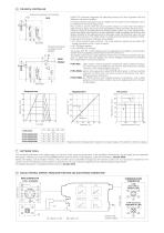
P/Q DIGITAL CONTROLLER Pressure transducer not included Digital P/Q controller integrates the alternate pressure and flow regulation with the electronic max power limitation. A remote pressure transducer must be installed on the system and its feedback has to be interfaced to the pump digital driver. Flow control is active when the actual system pressure is lower than the pressure reference input signal: the pump flow is regulated according to the flow reference input. Pressure control is activated when the actual pressure grows up to the pressure reference input signal: the pump flow is then...
Open the catalog to page 4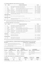
ELECTRONIC CONNECTIONS - Standard, Standard with /X and /C options PIN TECHNICAL SPECIFICATIONS Power supply 24 VDC for pilot valve’s solenoid power stage Input - power supply Power supply 0 VDC for pilot valve’s solenoid power stage Driver status: Fault (0VDC) or normal working (24 VDC) Output - on/off signal signal zero for MONITOR signals (pin 6,8) and INPUT+ signals (pin 5,7) Flow reference: ±10 VDC maximum range (4 ÷ 20 mA for /I option) Input - analog signal Flow monitor: ±10 VDC maximum range (4 ÷ 20 mA for /I option) Output - analog signal Pressure reference: ±10 VDC maximum range (4...
Open the catalog to page 5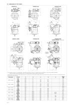
DIMENSIONS OF PVPC PUMPS VERSION CZ VERSION LZQZ VERSION LZQZR VERSION PERS VERSION PERS/X (dotted line) Pressure transducer (PERS/X) G¼" 2 ቢ = Regulation screw for max displacement. Adjustable range 50% to 100% of max displacement (not available for versions PES, PERS and PERS/X). In case of double pump the regulation screw is not always available, please contact our technical office. Drawing shows pumps with clockwise rotation (option D): pumps with counterclockwise rotation (option S) will have inlet and outlet ports inverted and consequently also the position of the control devices. Pump...
Open the catalog to page 6All ATOS catalogs and technical brochures
 Hydraulic filters
8 Pages
 Safety valves
11 Pages
 Technical leaflets TE
16 Pages
 Technical leaflets TC
16 Pages
 Technical leaflets TX
6 Pages
 Technical leaflets TZ
16 Pages
 PFE-31, PFE-41, PFE-51
4 Pages
 Hand pumps type PM
2 Pages
 Double vane pumps
4 Pages
 PFEO-41 and PFEDO-43
4 Pages


Archived catalogs
 Servo proportional valves
8 Pages
- Control valve
- Cylinder
- Liquid filter
- Flap valve
- Check valve
- Directional control valve
- Double-acting cylinder
- Hydraulic pump
- Filter with cartridge
- Hydraulic cylinder
- Piston actuator valve
- Oil valve
- Hydraulic valve
- 2-channel valve
- Hydraulic directional control valve
- Flow control valve
- Pack unit
- Hydraulic piston pump
- Pneumatic directional control valve