- Products
- Catalogs
- News & Trends
- Exhibitions
Proportional directional valves type DHZO-AES and DKZOR-AES
1 /9Pages

Proportional directional valves type DHZO-AES and DKZOR-AES
1 /9Pages
Catalog excerpts
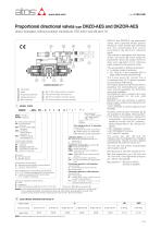
Proportional directional valves type DHZO-AES and DKZOR-AES direct operated, without position transducer, ISO 4401 size 06 and 10 DHZO-A* and DKZOR-A* are proportional valves, direct operated without position transducer, which provide both directional and non-compensated flow control according to the electronic reference signal. They operate in association with electronic drivers, see section ,ݘwhich supply the proportional valves with proper current to align valve regulation to the reference signal supplied to the electronic driver. They are available in different executions: • -A, without position transducer; • -AE, -AES as -A plus analogue (AE) or digital (AES) integral electronics ብ; The 4-way spool ባ , sliding into a 5-chambers body ቢ, is directly operated by proportional solenoids ቤ. The integral electronics ብ ensures factory presetting, fine functionality plus valve-tovalve interchangeability and simplified wiring and installation. The electronic main connector ܭis fully interchangeable for -AE and -AES executions. Standard 7 pin main connector is used for power supply, analog input reference and monitor signals. 12 pin connector is used for options /Z and /W (AES). Valve body Spool Proportional solenoid Integral electronics Main connector -BC or -BP communication connector -PS communication connector (3) -EH Communication connector (input) -EH Communication connector (output) MODEL CODE * Seals material: omit for NBR (mineral oil & water glycol) PE = FPM DHZO = size 06 DKZOR = size 10 Series number A = without position transducer AE = as A plus integral electronics AES = as A plus integral digital electronics AEG = as AES plus internal reference generation (1) AEZ = as AES plus internal cycle generation (2) Coil voltage (only for -A execution) see section :ݜ - = standard coil for 24VDC Atos drivers 6 = optional coil for 12VDC Atos drivers 18 = optional coil for low current drivers Hydraulic options, see section :ݚ B = solenoid and integral electronics at side of port A Y = external drain Options for -A execution see section :ݜ MO = horizontal hand lever MV = vertical hand lever BMO= horizontal hand lever installed at side of port A BMV= vertical hand lever installed at side of port A N = manual micrometric adjustment NV = as N plus handwheel and graduated scale Electronics options for -AE execution see section :ݞ I = current reference input (4÷20 mA) Q = enable signal Electronics options for -AES execution see section 10 : Q = enable signal Z = double power supply, enable fault and monitor (12 pin connector) W = power limitation function (12 pin connector) see section 10.3 Communication interfaces (only for digital electronics) PS = Serial (3) BC = CANopen (only AES) BP = PROFIBUS DP (only AES) EH = EtherCAT (only AES) Valve size 0 = ISO 4401 size 06 1 = ISO 4401 size 10 Configuration, see section ݙ 5 = external plus central position, spring centered 7 = 3 position, spring centered Spool overlapping in central position, see section ݙ 1 = P, A, B, T positive overlapping (20% of spool stroke) 3 = P positive overlapping; (20% of spool stroke) A, B, T, negative overlapping Spool type (regulating characteristics) L = linear; S = progressive; D = differential-progressive (as S, but with P-A= Q, P-B= Q/2) Following communication interfaces ቧ, ቨ are available for the digital -AES execution: • -PS, Serial communication interface for configuration, monitoring and firmware updating through Atos PC software always present also for -BC, -BP and -EH options. • -BC, CANopen interface • -BP, PROFIBUS DP interface • -EH, EtherCAT interface The valves with -BC, -BP and -EH interfaces can be integrated into a fieldbus communication network and thus digitally operated by the machine control unit. The coils are fully plastic encapsulated with insulation class H. Mounting surface: ISO 4401 sizes 06 and 10. Max flow respectively up to 50 l/min and 105 l/min with valve differential pressure Δp = 30 bar, see table .ݙ Max pressure = 350 bar for DHZO; 315 bar for DKZOR. Spool size: 14, 1, 3, 5 = see section ݙ Notes: (1) For detailed description of proportional valves with AEG internal reference generation, see tab. F220 (2) For detailed description of proportional valves with AEZ internal cycle generation, see tab. F220 (3) Serial communication interface always present, also for -BC, -BP and -EH options ELECTRONIC DRIVERS FOR DHZO-A* -A Valve model Drivers model Data sheet Note: For power supply and communication connector see section
Open the catalog to page 1
HYDRAULIC CHARACTERISTICS (based on mineral oil ISO VG 46 at 50 °C) Hydraulic symbols Valve model Spool overlapping Spool type and size Pressure limits Max flow (1) at Δp = 10 bar (P-T) at Δp = 30 bar (P-T) at Δp = 70 bar (P-T) Response time (2) T = 210 (250 with external drain /Y) 17 30 45 Notes: Ȝ Above performance data refer to valves coupled with Atos electronic drivers, see section .ݘ Ȝ The flow regulated by the directional proportional valves is not pressure compensated, thus it is affected by the load variations.To keep costant the regulated flow under different load conditions, modular...
Open the catalog to page 2
ANALOG INTEGRAL DRIVERS -AE - OPTIONS Standard driver execution provides on the 7 pin main connector: Power supply - 24VDC must be appropriately stabilized or rectified and filtered; a 2,5 A safety fuse is required in series to the driver power supply. Apply at least a 10000 μF/40 V capacitance to single phase rectifiers or a 4700 μF/40 V capacitance to three phase rectifiers Reference input signal - analog differential input with ±10 VDC nominal range (pin D, E), proportional to desired coil current Monitor output signal - analog output signal proportional to the actual valve’s coil current...
Open the catalog to page 3
DIGITAL INTEGRAL DRIVERS -AES - OPTIONS Standard driver execution provides on the 7 pin main connector: Power supply - 24VDC must be appropriately stabilized or rectified and filtered; a 2,5 A safety fuse is required in series to each driver power supply Apply at least a 10000 μF/40 V capacitance to single phase rectifiers or a 4700 μF/40 V capacitance to three phase rectifiers. Reference input signal - analog differential input with ±10VDC nominal range (pin D,E), proportional to desired coil current (4÷20 mA with cable break detection, ±10 mA, ±20 mA or 0÷20 mA software selectable) Monitor...
Open the catalog to page 4All ATOS catalogs and technical brochures
 Hydraulic filters
8 Pages
 Safety valves
11 Pages
 Technical leaflets TE
16 Pages
 Technical leaflets TC
16 Pages
 Technical leaflets TX
6 Pages
 Technical leaflets TZ
16 Pages
 PFE-31, PFE-41, PFE-51
4 Pages
 Hand pumps type PM
2 Pages
 Double vane pumps
4 Pages
 PVPC pumps
6 Pages
 PFEO-41 and PFEDO-43
4 Pages


Archived catalogs
 Servo proportional valves
8 Pages
- Control valve
- Cylinder
- Liquid filter
- Flap valve
- Check valve
- Directional control valve
- Double-acting cylinder
- Hydraulic pump
- Filter with cartridge
- Hydraulic cylinder
- Piston actuator valve
- Oil valve
- Hydraulic valve
- 2-channel valve
- Hydraulic directional control valve
- Flow control valve
- Pack unit
- Hydraulic piston pump
- Pneumatic directional control valve