- Products
- Catalogs
- News & Trends
- Exhibitions
PFEO-41 and PFEDO-43
1 /4Pages

PFEO-41 and PFEDO-43
1 /4Pages
Catalog excerpts
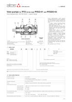
Vane pumps for PTO drives type PFEO-41 and PFEDO-43 fixed displacement, DIN ISO 6162-1, square flange Hydraulic symbol body first cartridge: stator, rotor, vanes, balanced plates second cartridge: as above renforced shaft double ball bearing Fixed displacement vane pumps specially designed for direct installation on PTO drives of mobile vehicles and derived from PFE standard versions but with: - 4 holes, square mounting flange according to DIN ISO 6162-1 for direct connection to PTO; - DIN 5462 reinforced splined shaft, specially supported by a double ball bearing and a roll bearing for high radial loads; - double shaft seal to prevent contamination between the PTO gearbox fluid and the pump fluid. They are available in single cartridge execution (PFEO) or with double cartridge in a single body (PFEDO). Easy installation due to the possibility of inlet/outlet ports orientation and semplified maintenance due to the quick cartridge replacement. Wide displacement range: from 29 to 85 cm3/rev for PFEO, from 29+16 to 85+44 for PFEDO. Max pressure up to 210 bar. roll bearing double shaft seal inlet port first outlet port second outlet port MODEL CODE /* Seals material: omit for NBR (mineral oil & water glycol) PE = FPM = fixed displacement vane pump PFEDO = fixed displacement double vane pump PFEO Series number Models: 41 = for PFEO, see section ݙ 43 = for PFEDO, see section ݚ Ports orientation, see section ݛ Direction of rotation (viewed at the shaft end): D = clockwise (supplied standard if not otherwise specified) S = counterclockwise Displacement [cm3/rev] PFEO, see section .ݙ Displacement of first element [cm3/rev] PFEDO, see section .ݚ Note: PFEO and PFEDO are not reversible Displacement of second element [cm3/rev], PFEDO, see section .ݚ Drive shaft, splined type DIN 5462. Note: model type PFEO-42* with max pressure up to 280 bar with displacement 045, 056, 070 and 085, available on request. MAIN CHARACTERISTICS Installation position Axial loads are not allowed. For max allowed radial load see diagram 7 in section ݜ Ambient temperature Hydraulic oil as per DIN 51524...535; for other fluids see section ݗ Recommended viscosity max at cold start max at full power during operation min at full power Fluid contamination class Fluid temperature 1000 mm2/s (low speed 400 rpm and low pressure recommended) 100 mm2/s 24 mm2/s 10 mm2/s ISO 4401 class 21/19/16 NAS 1638 class 10 (filters at 25 µm value with ß25 ≥ 75 recommended) -20°C +60°C -20°C +50°C (water glycol) Recommended suction line pressure from -0,5 to 1,5 bar for speed up to 1800 rpm; from 0 to +1,5 bar for speed over 1800 rpm A009
Open the catalog to page 1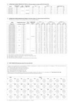
OPERATING CHARACTERISTICS OF PFEO at 1450 rpm (based on mineral oil ISO VG 46 at 50°C) Model OPERATING CHARACTERISTICS OF PFEDO at 1450 rpm (based on mineral oil ISO VG 46 at 50°C) PFEDO-43 are composed of one cartridge PFE-41 and one cartridge PFED-31. Max pressure (1) Max Speed range pressure (1) rpm (2)(3) Speed range min/max (2) rpm (3) Max pressure is 160 bar for /PE version and water glycol fluid Max speed is 1800 rpm for /PE version; 1500 rpm for water glycol fluid Max speed for venting = 2700 rpm Flow rate and power consumption are proportional to the rotation speed PORT ORIENTATION (pumps...
Open the catalog to page 2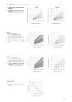
DIAGRAMS (based on mineral oil ISO VG 46 at 50°C) 2 = Torque versus pressure diagram PFEDO-43 (the total shaft torque is the sum of the first cartridge + the second one). PFEDO-43 Torque needed to operate the pump [Nm] 1 = Torque versus pressure diagram PFEO-41 Torque needed to operate the pump [Nm] 3 = Flow versus speed diagram with pressure variation from 7 bar to 210 bar. 4 = Power consumption versus speed diagram at 140 bar. Power consumption is proportional to operating pressure. Flow [l/min] PFEO-41 PFEDO-43: First element (cartridge SC-PFE-41**) PFEDO-43: Second element (cartridge SC-PFED-31**)...
Open the catalog to page 3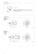
DRIVE SHAFT The total torque applied to the shaft of the pump is the sum of the single torque needed for operating each single cartridge and it is necessary to verify that this total torque applied to the drive shaft is not higher than max allowed. The values of torque needed to operate each single cartridge are shown on the "torque versus pressure diagram" at section .ݜ PFEO-41* Mounting flange DIN ISO 6162-1; SAE J518 “C” SAE flanges port P = 1” port T = 11/2” PFEDO-43* Mounting flange DIN ISO 6162-1; SAE J518 “C” SAE flanges port P1 = 1” port P2 = 3/4” port T = 21/2”
Open the catalog to page 4All ATOS catalogs and technical brochures
 Hydraulic filters
8 Pages
 Safety valves
11 Pages
 Technical leaflets TE
16 Pages
 Technical leaflets TC
16 Pages
 Technical leaflets TX
6 Pages
 Technical leaflets TZ
16 Pages
 PFE-31, PFE-41, PFE-51
4 Pages
 Hand pumps type PM
2 Pages
 Double vane pumps
4 Pages
 PVPC pumps
6 Pages


Archived catalogs
 Servo proportional valves
8 Pages
- Valve
- Control valve
- Cylinder
- Liquid filter
- Flap valve
- Check valve
- Directional control valve
- Double-acting cylinder
- Hydraulic pump
- Filter with cartridge
- Hydraulic cylinder
- Piston actuator valve
- Oil valve
- Hydraulic valve
- 2-channel valve
- Hydraulic directional control valve
- Flow control valve
- Pack unit
- Hydraulic piston pump
- Pneumatic directional control valve