- Products
- Catalogs
- News & Trends
- Exhibitions
Modular cartridge valves type LIDEW, LIDBH
1 /4Pages

Modular cartridge valves type LIDEW, LIDBH
1 /4Pages
Catalog excerpts
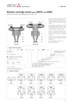
Modular cartridge valves type LIDEW and LIDBH directional control, ISO 7368 sizes from 16 to 100 LID* are directional control valves composed by a 2-way cartridge housed in a recess of standard dimensions and by a closing functional element ቢ called “cover”. These valves are available in standard sizes 16 to 100 according to ISO 7368 (DIN 24342). The flow is inhibited or permitted according to a proper pilot control; cracking pressure value depends on poppet spring ብ. Flow up to 8000 l/min at Δp = 6 bar. Pressure up to 350 bar. The cartridge is composed by a poppet ባ hydraulically piloted by means of internal connections in the cover (X, Z1, Z2, F, Y) and sliding into a drilled sleeve ቤ. MODEL CODE FOR COVERS D = direct operated valve Seals material: omit for NBR (mineral oil & water glycol) PE = FPM EW** = with solenoid valve for pilot selection; BH** = as EW* but with shuttle valve for pilot selection. See section ݘfor configurations; Size: 1 = 16; 2 = 25; 3 = 32; * Optional different provision or setting of the calibrated plugs in the pilot channels, see section ݜ Series number Supply voltage, see section ݞ 00 = valve without coils X = without connector See section ݞfor available connectors, to be ordered separately Pilot valve (1) for cartridge size 1 to 6: -I = DHI for AC and DC supply, with CURUS certified solenoids -E = DHE for AC and DC supply, high performances -ER = DHER as DHE but with CURUS certified solenoids for cartridge size 8 and 10: -E = DKE for AC and DC supply For model code of poppet, see section ݙ (1) see note in section ݜfor other available pilot valves HYDRAULIC SYMBOLS
Open the catalog to page 1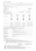
HYDRAULIC CHARACTERISTICS Poppet Size MODEL CODE FOR POPPETS, see section ݚfor function /* Seals material: omit for NBR (mineral oil & water glycol) PE = FPM Cartridge according to ISO 7368 Size, the same of relevant cover: 16 40 80 25 50 100 32 63 Design number Type of poppet, see section ݘfor maximum flow 32, 33 (size 16…100) 42 (size 16…80) = as 32 but with dumping nose 43 (size 16…100) = as 33 but with dumping nose 2 = 1,5 bar for poppet 32, 42; 3 = 3 bar for all poppets 6 = 5,5 bar for all poppets Spring cracking pressure: 1 = 0,3 bar for poppet 32, 42; 1 = 0,6 bar for poppet 33, 43;...
Open the catalog to page 2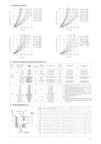
Flow [l/min] Flow [l/min] Flow [l/min] Flow [l/min] ELECTRIC FEATURES FOR AGAM WITH SOLENOID VALVE Solenoid valve type External supply nominal voltage ± 10% (1) Voltage code Power Type of consumption connector (3) Code of spare coil DHI Colour of coil label DHI Code of spare coil DHE Code of spare coil DHER green red black black yellow white light blue silver (1) For other supply voltages available on request see technical tables E010, E015. (2) Coil can be supplied also with 60 Hz of voltage frequency: in this case the performances are reduced by 10 ÷ 15% and the power consumption is 55 VA (DHI)...
Open the catalog to page 3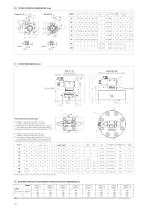
COVER INTERFACE DIMENSIONS [mm] Size 16 ÷ 63 Drawing of size 50 dotted line: example of double solenoid version Size 80 and 100 dotted line: example of AC solenoid verison Notes referred to the below table: (1) LIDEW1*: solenoid at side of port Y of cover; LIDEW2*: solenoid at side of port X of cover; (2) The position of external attachments Pp, Dr, Z1 and Z2 are inverted each others respect to the showed sketch (3) Hexagon socket head screw according to DIN 912-12.9 (1) LIDBH*A: solenoid at side of port X of cover; LIDBH*C: solenoid at side of port Y of cover; (2) The position of external attachments...
Open the catalog to page 4All ATOS catalogs and technical brochures
 Hydraulic filters
8 Pages
 Safety valves
11 Pages
 Technical leaflets TE
16 Pages
 Technical leaflets TC
16 Pages
 Technical leaflets TX
6 Pages
 Technical leaflets TZ
16 Pages
 PFE-31, PFE-41, PFE-51
4 Pages
 Hand pumps type PM
2 Pages
 Double vane pumps
4 Pages
 PVPC pumps
6 Pages
 PFEO-41 and PFEDO-43
4 Pages


Archived catalogs
 Servo proportional valves
8 Pages
- Cylinder
- Liquid filter
- Flap valve
- Check valve
- Directional control valve
- Double-acting cylinder
- Hydraulic pump
- Filter with cartridge
- Hydraulic cylinder
- Piston actuator valve
- Oil valve
- Hydraulic valve
- 2-channel valve
- Hydraulic directional control valve
- Flow control valve
- Pack unit
- Hydraulic piston pump
- Pneumatic directional control valve