- Products
- Catalogs
- News & Trends
- Exhibitions
Axis motions controllers type Z-ME-KZ
1 /8Pages

Axis motions controllers type Z-ME-KZ
1 /8Pages
Catalog excerpts
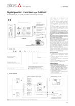
Digital position controllers type Z-ME-KZ Eurocard format, for electrohydraulic closed loop controls MAIN FUNCTIONS AND FEATURES USER INTERFACE SUPPLY 24V POSITION REFERENCE POSITION FEEDBACK Position control Alternated control Real-time fieldbus Serial port FORCE FEEDBACK AUXILIARY INPUT Internal reference DRIVER’S COMMAND Enhanced diagnostic AUXILIARY OUTPUT Z-SW-PS programming software MODEL CODE Electronic axis controller in Eurocard format Electrical Features: • 4 digits front panel display to check and change parameters as well as for diagnostics • Front panel DB9 connector for serial programming interface • Front panel test points for debug and maintenance • Eurocard format (DIN 41494 - Plug-in-units) • CE mark according to EMC directive Alternated position / force (or position / pressure) control module Series number Serial communication interface for configuration and monitoring function Software Features: • Internal generation of motion cycle • Setting of axis’s dynamic response (PID) to optimize the application performances • Software selectable range of electronic reference analog inputs: voltage or current • Enhanced diagnostics of the axis status • Intuitive graphic interface • In field firmware update through standard serial communication • Internal oscilloscope function Optional fieldbus communication interfaces: - = standard without fieldbus interface BC = CANopen communication interface BP = PROFIBUS DP communication interface BLOCK DIAGRAM DIGITAL CONTROLLER Z-ME-KZ SETPOINT GENERATOR POSITION CONTROL FIELDBUS NETWORK PROPORTIONAL VALVE SERIAL PORT Z-SW-PS SOFTWARE FORCE CONTROL DIGITAL I/O MACHINE CENTRAL UNIT Z-ME-KZ digital axis controllers perform the position closed loop of linear or rotative hydraulic axes. The controller receives a position feedback from the axis transducer and it generates a reference signal to the proportional valve which regulates the hydraulic flow to the actuator. The position feedback interfaces are SSI, incremental encoder, potentiometer or standard analog inputs (voltage or current) software selectable. A front panel serial port is always present for configuration and monitoring of the controller. The controller can be operated in real time by external or internally generated reference signal. With external reference signal the actuator’s motion cycle can be managed by either analog or fieldbus reference input. With internally generated reference signal the actuator’s motion cycle can be managed by external or fieldbus on/off commands. A pressure/force alternated control may be set by software additionally to the position control: a pressure/force transducer has to be assembled into the actuator and connected to the controller; a second reference pressure/force signal is required. Several auxiliary digital inputs/outputs are available and they can be used to synchronize other machine functions and to transmit information on the controller state. FORCE / PRESSURE FEEDBACK POSITION FEEDBACK HYDRAULIC ACTUATOR Note: Block diagram example for alternated position/force control, with fieldbus interface.
Open the catalog to page 1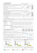
POSITION REFERENCE MODE 3.1 External reference generation External reference generation Z-ME-KZ controller regulates in closed loop the actuator position according to an external reference position signal and to the position feedback from the actuator transducer. It generates a reference signal for the proportional valve which regulates the hydraulic flow to the actuator. Analog (a) or Fieldbus (b) reference Machine central unit The external reference signal can be software selected among: Valve command and monitor Analog reference (a) The controller receives in real time the reference signal...
Open the catalog to page 2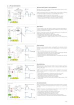
APPLICATION EXAMPLES Hydraulic steering wheel in marine applications Position control Position Rudder controls on motor yachts and sail boats requires smooth control for precise and reliable operations. Z-ME-KZ controllers perform the rudder position control system, ensuring accurate and repetitive regulations for a comfortable ride, thanks to: - analog position reference mode for real time controls - potentiometer position transducer for simple and compact solution - position PID control parameters to optimize the system response - complete diagnostic information for advanced system monitoring...
Open the catalog to page 3
Notes: (1) percentage of the total stroke; (2) provided by Z-ME-KZ controller; (3) magnetosonic transducer; for additional details contact Atos technical support.
Open the catalog to page 4
8 FRONT PANEL DESCRIPTION 9 FRONT PANEL VIEW 8.1 Keyboard and display On the Z-ME-KZ front panel are available 4 function keys (ESC, ENT, UP, DWN), and a numeric display (4 digits plus sign) to allow the user to view and change the controller’s parameters as well as to display diagnostic messages. The following parameters can be accessed (viewed or changed) via corresponding menu structure: - command and actual values - analog input / output values - digital input / output status - position sensor indication - force / pressure sensor indication Parameter’s changes of the configuration, control...
Open the catalog to page 5
SIGNAL SPECIFICATIONS Atos digital controllers are CE marked according to the applicable directives (e.g. Immunity/Emission EMC Directive). Installation, wirings and start-up procedures must be performed according to the prescriptions shown in table F003 and in the user manuals included in the Z-SW programming software. The electrical signals of the controller (e.g. monitor signals) must not be directly used to activate safety functions, like to switch-ON/OFF the machine’s safety components, as prescribed by the European standards. 11.1 Power supply and wirings (V+ and V0) The power supply must...
Open the catalog to page 6
11.14 Digital input signals (DI1 - DI8) The 8 digital inputs can be used to trigger a command or to read a system state. For each input by the Z-SW software, it is possible to set the polarity and to match a proper condition within the following: - start/stop/switch-over command in case of internal reference generation (see 3.2) - specific operative command for hydraulic axis mode (referencing mode, jog mode, automatic mode) - jog command - disable pressure / force alternated control 11.15 Digital output signals (DO1 - DO7) The 7 digital outputs can be used to generate digital signals useful...
Open the catalog to page 7All ATOS catalogs and technical brochures
 Hydraulic filters
8 Pages
 Safety valves
11 Pages
 Technical leaflets TE
16 Pages
 Technical leaflets TC
16 Pages
 Technical leaflets TX
6 Pages
 Technical leaflets TZ
16 Pages
 PFE-31, PFE-41, PFE-51
4 Pages
 Hand pumps type PM
2 Pages
 Double vane pumps
4 Pages
 PVPC pumps
6 Pages
 PFEO-41 and PFEDO-43
4 Pages


Archived catalogs
 Servo proportional valves
8 Pages
- Control valve
- Cylinder
- Liquid filter
- Flap valve
- Check valve
- Directional control valve
- Double-acting cylinder
- Hydraulic pump
- Filter with cartridge
- Hydraulic cylinder
- Piston actuator valve
- Oil valve
- Hydraulic valve
- 2-channel valve
- Hydraulic directional control valve
- Flow control valve
- Pack unit
- Hydraulic piston pump
- Pneumatic directional control valve