- Products
- Catalogs
- News & Trends
- Exhibitions
Axis motions controllers type Z-ME-KZ/GI
1 /8Pages

Axis motions controllers type Z-ME-KZ/GI
1 /8Pages
Catalog excerpts
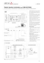
Plastic injection controllers type Z-ME-KZ-PS/GI Eurocard format, for electrohydraulic closed loop controls of injection in plastic presses MAIN FUNCTIONS AND FEATURES USER INTERFACE SUPPLY 24V VELOCITY REFERENCE POSITION FEEDBACK Real-time fieldbus Injection process PRESSURE FEEDBACK AUXILIARY INPUT Serial port Velocity control DRIVER’S COMMAND Enhanced diagnostic AUXILIARY OUTPUT Z-SW-PS programming software MODEL CODE Electronic axis controller in Eurocard format Electrical Features: • 4 digits front panel display to check and change parameters as well as for diagnostics • Front panel DB9 connector for serial programming interface • Front panel test points for debug and maintenance • Eurocard format (DIN 41494 - Plug-in-units) • CE mark according to EMC directive Alternated position / velocity / force control module Series number Injection process control Optional fieldbus communication interfaces: - = standard without fieldbus interface BC = CANopen communication interface BP = PROFIBUS DP communication interface Serial communication interface for configuration and monitoring function Z-ME-KZ-PS/GI plastic injection controllers perform velocity and force closed loop controls, according to real time commands (analog or fieldbus) generated by machine control unit (e.g. PLC). The controller receives position / pressure feedbacks and generates reference signal to the proportional valve which regulates the hydraulic flow to the injection actuator. The position feedback signal is software selectable: SSI, incremental encoder, potentiometer or analog (voltage or current). Remote pressure transducers have to be remotely installed close to the injection actuator and connected to the controller (see section 5 ). The machine electronic control unit manages the injection process through dedicated digital commands or fieldbus communication. Serial and Profibus (only for /BP option) ports are available on the front panel for controller configuration and diagnostics. Software Features: • Internal generation of injection cycle • Setting of axis’s dynamic response (PID) to optimize the injection performances • Monitoring of injection process • Software selectable range of electronic reference analog inputs: voltage or current • Diagnostics of the injection status • Intuitive graphic interface • In field firmware update through standard serial communication port • Internal oscilloscope function BLOCK DIAGRAM DIGITAL CONTROLLER Z-ME-KZ-PS/GI PLASTIC INJECTION SYSTEM SERIAL PORT Z-SW-PS SOFTWARE INJECTION PROCESS VELOCITY CONTROL PROPORTIONAL VALVE FIELDBUS NETWORK PRESSURE CONTROL MONITOR HYDRAULIC INJECTION ACTUATOR PRESSURE FEEDBACK MACHINE CENTRAL UNIT DIGITAL I/O POSITION FEEDBACK Note: Block diagram example with fieldbus interface.
Open the catalog to page 1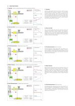
INJECTION PHASES 3.1 Injection - Velocity closed loop control with max pressure limitation Feedback Reference Force Transfer Injection phase starts when the machine control unit (e.g. PLC) enables the command “Injection”. The controller performs velocity closed loop profile according to the external velocity reference, with a maximum force limitation during traversing. Machine control unit provides velocity step reference to the controller, which internally limits acceleration and deceleration in order to avoid mechanicals stress during velocity variations 3.2 Pack and Hold - Pressure closed...
Open the catalog to page 2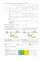
EXAMPLE OF INJECTION CYCLE WITH DIGITAL COMMANDS FROM MACHINE CENTRAL UNIT PACK AND HOLD BACK PRESSURE Injection condition Force Transfer condition Decompression condition Time Feedback Reference (*) Note : See section 11 for digital inputs commands connection Note : For controllers with /BP or /BC option the injection cycle is managed by fieldbus commands 5 PRESSURE / FORCE CONFIGURATION For technical support about proportional valve selection and control electronic configuration, please contact Atos tech assistance at [email protected] Alternated Velocity/Pressure Control - One pressure...
Open the catalog to page 3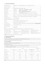
CONTROLLER CHARACTERISTICS Position transducer SSI, incremental encoder, potentiometer, analog Input range : Analog Inputs voltage ±10 VDC - input impedance: Ri > 100 kW current 0 ÷ 20 mA - input impedance: Ri < 500 W voltage ±10 VDC @ max 10 mA current 0 ÷ 20 mA @ max 500 W load resistance 0 ÷ 5 VDC (OFF state), 16 ÷ 24 VDC (ON state), 5 ÷ 16 VDC (not accepted); Input impedance: Ri > 10 kW Output range : Analog Outputs Input range : Digital Inputs Rectified and filtered: VRMS = 20 ÷ 32 VMAX (ripple max 10 % VPP) Digital Outputs (*) Output range : 0 ÷ 24 VDC ( ON state > [power supply - 2 V]...
Open the catalog to page 4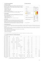
9 FRONT PANEL DESCRIPTION 10 FRONT PANEL VIEW 9.1 Keyboard and display On the Z-ME-KZ-PS/GI front panel are available 4 function keys (ESC, ENT, UP, DWN), and a numeric display (4 digits plus sign) to allow the user to view and change the controller’s parameters as well as to display diagnostic messages. The following parameters can be accessed (viewed or changed) via corresponding menu structure: - command and actual values - analog input / output values - digital input / output status - position sensor indication - force / pressure sensor indication Parameter’s changes of the configuration,...
Open the catalog to page 5
SIGNAL SPECIFICATIONS Atos digital controllers are CE marked according to the applicable directives (e.g. Immunity/Emission EMC Directive). Installation, wirings and start-up procedures must be performed according to the prescriptions shown in table F003 and in the user manuals included in the Z-SW programming software. The electrical signals of the controller (e.g. monitor signals) must not be directly used to activate safety functions, like to switch-ON/OFF the machine’s safety components, as prescribed by the European standards. 12.1 Power supply and wirings (V+ and V0) The power supply must...
Open the catalog to page 6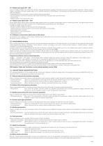
12.13 Digital input signals (DI1 - DI8) Five pre-configured digital inputs (DI3, DI4, DI6, DI7, DI8) are dedicated to manage of the injection process, while two digital inputs (DI1, DI5) are used to trigger a command or to read a system state. For DI1 and DI5 input by the Z-SW software, it is possible to set the polarity and to match a proper condition within the following: - start/stop/switch-over command in case of internal reference generation - specific operative command for hydraulic axis mode (referencing mode, jog mode, automatic mode) - jog command - disable pressure / force alternated...
Open the catalog to page 7All ATOS catalogs and technical brochures
 Hydraulic filters
8 Pages
 Safety valves
11 Pages
 Technical leaflets TE
16 Pages
 Technical leaflets TC
16 Pages
 Technical leaflets TX
6 Pages
 Technical leaflets TZ
16 Pages
 PFE-31, PFE-41, PFE-51
4 Pages
 Hand pumps type PM
2 Pages
 Double vane pumps
4 Pages
 PVPC pumps
6 Pages
 PFEO-41 and PFEDO-43
4 Pages


Archived catalogs
 Servo proportional valves
8 Pages
- Control valve
- Cylinder
- Liquid filter
- Flap valve
- Check valve
- Directional control valve
- Double-acting cylinder
- Hydraulic pump
- Filter with cartridge
- Hydraulic cylinder
- Piston actuator valve
- Oil valve
- Hydraulic valve
- 2-channel valve
- Hydraulic directional control valve
- Flow control valve
- Pack unit
- Hydraulic piston pump
- Pneumatic directional control valve