ATA6020N Watchdog IC, µP Based, Programmable Via Metal Mask (Based on the ATAR080 Microcontroller)
1 /68Pages

ATA6020N Watchdog IC, µP Based, Programmable Via Metal Mask (Based on the ATAR080 Microcontroller)
1 /68Pages
Catalog excerpts
ATA6020N Low-current Microcontroller for Watchdog Function DATASHEET Programmable system clock with prescaler and three different clock sources Very low sleep current (< 1µA) Very low power consumption in active, power-down and sleep mode 2-Kbyte ROM, 256 × 4-bit RAM 12 bi-directional I/Os Up to 6 external/internal interrupt sources Synchronous serial interface (2-wire, 3-wire) Multifunction timer/counter with ● Watchdog, POR and brown-out function ● Voltage monitoring inclusive Lo_BAT detection ● Flash controller ATAM893 available (SSO20) ● Code-efficient instruction set ● High-level language programming with qFORTH compiler Description The Atmel® ATA6020N is a member of Atmel 4-bit single-chip microcontroller family. It contains ROM, RAM, parallel I/O ports, one 8-bit programmable multifunction timer/counter with modulator function, voltage supervisor, interval timer with watchdog function and a sophisticated on-chip clock generation with external clock input and integrated RC-oscillators.
Open the catalog to page 1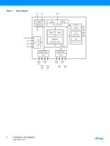
Brown-out protect RESET Voltage monitor External input External clock input UTCM Clock management T2I Timer 1 interval and watchdog timer Data direction Timer 2 8/12 bit timer with modulator Data direction + altemate function Data direction + internal control
Open the catalog to page 2
Pin Configuration Figure 1-1. Pinning SSO20 Package VDD Pin Description Type Function Alternate Function Reset State Supply voltage Circuit ground Bi-directional I/O line of port 2.0 NTE test mode enable, see also Section 3.2 “Master Reset” on page 11' Bi-directional I/O line of port 2.1 – Bi-directional I/O line of port 2.2 – Bi-directional I/O line of port 2.3 – Bi-directional I/O line of port 4.0 SC serial clock or INT3 external interrupt input Bi-directional I/O line of port 4.1 VMI voltage monitor input or T2I external clock input Timer 2 Bi-directional I/O line of port 4.2 T2O Timer 2 output...
Open the catalog to page 3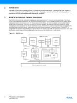
Introduction The Atmel® ATA6020N is a member of Atmel 4-bit single-chip microcontroller family. It contains ROM, RAM, parallel I/O ports, one 8-bit programmable multifunction timer/counter, voltage supervisor, interval timer with watchdog function and a sophisticated on-chip clock generation with integrated RC-oscillators. MARC4 Architecture General Description The MARC4 microcontroller consists of an advanced stack-based, 4-bit CPU core and on-chip peripherals. The CPU is based on the HARVARD architecture with physically separated program memory (ROM) and data memory (RAM). Three independent...
Open the catalog to page 4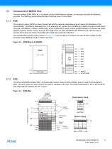
Components of MARC4 Core The core contains ROM, RAM, ALU, a program counter, RAM address registers, an instruction decoder and interrupt controller. The following sections describe each functional block in more detail. ROM The program memory (ROM) is mask programmed with the customer application program during the fabrication of the microcontroller. The ROM is addressed by a 12-bit wide program counter, thus predefining a maximum program bank size of 2-Kbytes. An additional 1-Kbyte of ROM exists, which is reserved for quality control self-test software The lowest user ROM address segment is taken...
Open the catalog to page 5
3.1.2.1 Expression Stack The 4-bit wide expression stack is addressed with the expression stack pointer (SP). All arithmetic, I/O and memory reference operations take their operands, and return their results to the expression stack. The MARC4 performs the operations with the top of stack items (TOS and TOS-1). The TOS register contains the top element of the expression stack and works in the same way as an accumulator. This stack is also used for passing parameters between subroutines and as a scratch pad area for temporary storage of data. 3.1.2.2 Return Stack The 12-bit wide return stack is...
Open the catalog to page 6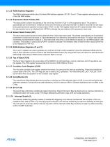
3.1.3.2 RAM Address Registers The RAM is addressed with the four 8-bit wide RAM address registers: SP, RP, X and Y. These registers allow access to any of the 256 RAM nibbles. 3.1.3.3 Expression Stack Pointer (SP) The stack pointer contains the address of the next-to-top 4-bit item (TOS-1) of the expression stack. The pointer is automatically pre-incremented if a nibble is moved onto the stack or post-decremented if a nibble is removed from the stack. Every post-decrement operation moves the item (TOS-1) to the TOS register before the SP is decremented. After a reset, the stack pointer has to...
Open the catalog to page 7
ALU The 4-bit ALU performs all the arithmetic, logical, shift and rotate operations with the top two elements of the expression stack (TOS and TOS-1) and returns the result to the TOS. The ALU operations affects the carry/borrow and branch flag in the condition code register (CCR). Figure 3-5. ALU Zero-address Operations RAM I/O Bus The I/O ports and the registers of the peripheral modules are I/O mapped. All communication between the core and the onchip peripherals take place via the I/O bus and the associated I/O control. With the MARC4 IN and OUT instructions, the I/O bus allows a direct read...
Open the catalog to page 8
Figure 3-6. Interrupt Handling INT7 Priority Level Main/ Autosleep 3.1.7.1 Interrupt Processing In order to process the eight interrupt levels, the MARC4 includes an interrupt controller with two 8-bit wide interrupt pending and interrupt active registers. The interrupt controller samples all interrupt requests during every non-I/O instruction cycle and latches these in the interrupt pending register. If no higher priority interrupt is present in the interrupt active register, it signals the CPU to interrupt the current program execution. If the interrupt enable bit is set, the processor enters...
Open the catalog to page 9
3.1.7.2 Interrupt Latency The interrupt latency is the time from the occurrence of the interrupt to the interrupt service routine being activated. This is extremely short (taking between 3 to 5 machine cycles depending on the state of the core). Table 3-1. Interrupt Priority Table Interrupt Opcode External hardware interrupt, any edge at BP52 or BP53 SSI interrupt or external hardware interrupt at BP40 or BP43 External hardware interrupt, at any edge at BP50 or BP51 Voltage monitor (VM) interrupt Hardware Interrupts Interrupt Mask Interrupt Source SSI buffer full/empty or BP40/BP43 interrupt...
Open the catalog to page 10All Atmel catalogs and technical brochures
 32-bit Microcontrollers
20 Pages
 MCUs Driving Displays
12 Pages
 Touch and 3D Gesture Control
12 Pages
 16-bit MCUs and DSCs
20 Pages
 XLP PIC® MCUs
8 Pages
 8-bit MCUs
16 Pages
 AT93C56B/66B Automotive
17 Pages
 Atmel AT86RF215 Device Family
235 Pages
 AT24C01C/02C
22 Pages
 maXTouch U Series - Flyer
2 Pages


Archived catalogs
 tinyAVR ATtiny24/44/84 Preliminary
240 Pages
 ATmega164P/324P/644P Preliminary
440 Pages
 ATmega48P/88P/168P/328P Preliminary
426 Pages
 ATmega1284P Preliminary
356 Pages
 AT90PWM216/316
359 Pages
 AT90PWM2, AT90PWM3, AT90PWM2B, AT90PWM3B
361 Pages
 ATmega329/3290/649/6490 Preliminary
392 Pages
 ATmega329P/3290P Preliminary
388 Pages
 AT90CAN32/64/128
428 Pages
 AT86RF230 Preliminary
98 Pages
 ATmega48/88/168 Automotive
335 Pages
 ATtiny25, ATtiny45, ATtiny85 Automotive
192 Pages
 ATtiny24/44/84 Automotive Preliminary
225 Pages
 AT86RF231 Preliminary
180 Pages
 Biometrics (Fingerprint Sensor)
20 Pages


- Transceiver module
- Potentiometer
- Industrial converter
- Ethernet transceiver
- Analog potentiometer
- Low-noise amplifier
- Analog amplifier
- Analog converter
- Circuit board
- Operational amplifier
- 32-bit microcontroller
- Low-power microcontroller
- Analog microcontroller
- High-speed converter
- General purpose microcontroller
- DAC converter
- Communication microcontroller
- High-speed amplifier
- ARM microcontroller