ATA5575M2 Read/Write LF RFID OTP IDIC 100 to 150kHz for ISO 11784 and ISO 11785 applications in FDX-B and FDX-A mode in the Animal Identification segment
1 /25Pages

ATA5575M2 Read/Write LF RFID OTP IDIC 100 to 150kHz for ISO 11784 and ISO 11785 applications in FDX-B and FDX-A mode in the Animal Identification segment
1 /25Pages
Catalog excerpts
ATA5575M2 Read/Write LF RFID IDIC 100kHz to 150kHz DATASHEET Features ● Contactless power supply ● Contactless read/write data transmission ● Radio frequency fRF from 100kHz to 150kHz ● 128-bit EEPROM user memory: 16 Bytes (8 Bits each) ● 8-bit configuration memory ● High Q-antenna tolerance due to built-in options ● Applications ● Animal ID, waste management, industrial identification ● ISO/IEC 11784/785 compatibility ● FDX-A ● FDX-B ● On-chip trimmed antenna capacitor ● 330pF ±3% ● 250pF ±3% ● Mega pads 200µm x 400µm ● Mega pads 200µm x 400µm with 25µm gold bumps for direct coil bonding ● Other options: ● Direct access mode
Open the catalog to page 1
Description The Atmel® ATA5575M2 is a contactless read/write identification IC (IDIC®) for applications in the 100-kHz to 150-kHz frequency band. A single coil connected to the chip serves as the IC's power supply and bi-directional communication interface. This antenna coil together with the chip form a transponder or tag. The on-chip 128-bit User EEPROM (16 bytes with 8 bits each) can be read and written byte-wise from a base station (reader). Data is transmitted from the IDIC (uplink) using load modulation. This is achieved by damping the RF field with a resistive load between the two terminals...
Open the catalog to page 2
Analog Front End (AFE) The AFE includes all circuits which are connected directly to the coil terminals. The AFE generates the IC power supply and handles bi-directional data communication with the reader. The AFE consists of the following blocks: ● Rectifier to generate a DC supply voltage from the AC coil voltage Clock extractor Switchable load between Coil 1 and Coil 2 for data transmission from tag to the reader Field-gap detector for data transmission from the base station to the tag ESD protection circuitry Data Rate Generator The data rate of the Atmel ATA5575M2 is programmable to operate...
Open the catalog to page 3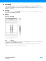
Mode Register The mode register maintains a readable shadow copy of the configuration data held in byte 16 of the EEPROM. It is continually refreshed during read mode and (re-)loaded after every POR event or reset command. Depending on the version, upon leaving the Atmel® factory site, the configuration data is pre-programmed according to Table 10-1 on page 18 and Table 10-4 on page 20. Modulator The modulator encodes the serialized EEPROM data for transmission to a tag reader or base station. Two types of encoding are implemented: Differential Biphase and FSK. User data User data User data User...
Open the catalog to page 4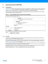
Configuration The Atmel® ATA5575M2 is mainly designed for ISO11784/11785 applications. It supports FDX-A and FDX-B mode (see also Figure 7-1 on page 14 for the structure of a FDX-B telegram typically used for animal ID applications). The configuration register, byte 16, enables the customer to configure the chip according to the individual application. In delivery state the default configuration is memory reprogrammable, read user data in diff. biphase RF/32 and ID length 128 bit which leads to the byte value '00001001b'. Table 5-1. 1 Atmel ATA5575M2: Byte 16 Configuration Register Mapping 3...
Open the catalog to page 5
Modulation The modulator consists of data encoders for the following types of modulation. Table 5-2. Atmel ATA5575M2: Types of Modulation Differential bi-phase Direct Data Output Encoding Transition at each bit start 0 creates an additional mid-bit change ID Length The Atmel® ATA5575M2 offers settings for different ID lengths. If bit 8 of byte 16 is set to '1', the ID length is 128 bits. Depending on the modulation scheme, resetting bit 8 of byte 16 to '0' leads either to the ID length of 64 bit with differential biphase coding or to the ID length of 96 bit with FSK2 coding respectively. Animal...
Open the catalog to page 6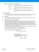
Figure 5-1. Examples of Different ID Length Settings ID Length = ‘0’ with diff. Bi-phase coding ID Length = ‘0’ with FSK2 coding Loading byte 16 ID Length = ‘1’ Byte-read Mode With the direct access command, only the addressed byte is read repetitively. This mode is called byte-read mode. Direct access is entered by transmitting the opcode ('10'), a single 0 bit, and the requested 5-bit byte address. Dummy Data The dummy data are a predefined bit sequence of all bits set to value '0'. This sequence is read out instead of the data stored in the user memory if the lock bits are set to '00000b'....
Open the catalog to page 7
Downlink Data Decoding Scheme Write data coding (gap separation) 1 data d1 50 58 All absolute times are given under the assumption TC = 1/fC = 8µs (fC = 125kHz) All absolute times assume TC = 1/fC = 8µs (fC = 125kHz) Downlink Data Protocol The Atmel® ATA5575M2 expects to receive a dual bit opcode as a part of a reader command sequence. There are three valid opcodes and overall five different commands (please refer to Figure 5-4 on page 9): ● The RESET opcode '00' starts an initialization cycle A single '10' opcode (Read ID) leads to reading the ID out of the EEPROM memory. This is suitable to...
Open the catalog to page 8
Figure 5-4. ATA5575M2 Command Formats OP Write byte Direct access Read upper bytes Reset command Programming When all necessary information has been received by the ATA5575M2, programming may proceed. There is a clock delay between the end of the writing sequence and the start of programming. Typical programming time is 5.6ms. This cycle includes a data verification read to grant secure and correct programming. After programming is successfully executed, the ATA5575M2 enters byte-read mode, transmitting the byte just programmed. If the command sequence is validated, the new data is programmed...
Open the catalog to page 9
Error Handling Several error conditions can be detected to ensure that only valid bits are programmed into the EEPROM. There are two error types which result into two different actions. Errors During Command Sequence The following detectable errors could occur when sending a command sequence to the Atmel® ATA5575M2: ● The wrong number of field clocks between two gaps (i.e., not a valid 1 or 0 pulse stream) The number of bits received in the command sequence is incorrect Bit Counts of Command Sequences Command Write byte Direct access Read upper bytes Reset command Errors Before/During Programming...
Open the catalog to page 10All Atmel catalogs and technical brochures
 32-bit Microcontrollers
20 Pages
 MCUs Driving Displays
12 Pages
 Touch and 3D Gesture Control
12 Pages
 16-bit MCUs and DSCs
20 Pages
 XLP PIC® MCUs
8 Pages
 8-bit MCUs
16 Pages
 AT93C56B/66B Automotive
17 Pages
 Atmel AT86RF215 Device Family
235 Pages
 AT24C01C/02C
22 Pages
 maXTouch U Series - Flyer
2 Pages


Archived catalogs
 tinyAVR ATtiny24/44/84 Preliminary
240 Pages
 ATmega164P/324P/644P Preliminary
440 Pages
 ATmega48P/88P/168P/328P Preliminary
426 Pages
 ATmega1284P Preliminary
356 Pages
 AT90PWM216/316
359 Pages
 AT90PWM2, AT90PWM3, AT90PWM2B, AT90PWM3B
361 Pages
 ATmega329/3290/649/6490 Preliminary
392 Pages
 ATmega329P/3290P Preliminary
388 Pages
 AT90CAN32/64/128
428 Pages
 AT86RF230 Preliminary
98 Pages
 ATmega48/88/168 Automotive
335 Pages
 ATtiny25, ATtiny45, ATtiny85 Automotive
192 Pages
 ATtiny24/44/84 Automotive Preliminary
225 Pages
 AT86RF231 Preliminary
180 Pages
 Biometrics (Fingerprint Sensor)
20 Pages


- Transceiver module
- Potentiometer
- Industrial converter
- Ethernet transceiver
- Analog potentiometer
- Low-noise amplifier
- Microcontroller
- Analog amplifier
- Analog converter
- Circuit board
- Operational amplifier
- 32-bit microcontroller
- Low-power microcontroller
- Analog microcontroller
- High-speed converter
- General purpose microcontroller
- DAC converter
- Communication microcontroller
- High-speed amplifier
- ARM microcontroller