ATA5551M-PPMY Standard Industrial/Consumer Read/Write Transponder
1 /28Pages

ATA5551M-PPMY Standard Industrial/Consumer Read/Write Transponder
1 /28Pages
Catalog excerpts

ATA5551M-PPMY Standard Read/Write ID Transponder with Anti-collision DATASHEET Features ● Read/write anti-collision ID transponder in plastic package ● Contactless read/write data transmission ● Inductive coupled power supply at 125kHz ● Basic component: R/W Atmel® IDIC® e5551 ● Anti-collision mode by password request ● E.g. 10 transponders read out in < 500ms (RF/32, Maxblock 2) depending on the application ● Built-in coil and capacitor for circuit antenna ● Starts with cyclical data read out ● 224-bit EEPROM user programmable in 32-bit blocks ● Typically < 50ms to write and verify a block ● Write protection by lock bits ● Malprogramming protection ● Options set by EEPROM ● Bit rate [bit/s]: RF/8, RF/16, RF/32, RF/40, RF/50, RF/64, RF/100, RF/128 ● Modulation: BIN, FSK, PSK, Manchester, bi-phase Application ● Access control systems ● Brand protection ● Process control and automation systems ● Installation and medical equipment ● Asset management systems ● Industrial
Open the catalog to page 1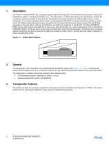
Description The Atmel® ATA5551M-PPMY is a completely programmable R/W transponder which implements all important functions for identification systems, including anti-collision (e.g., 10 transponders in < 500ms depending on the application). It allows the contactless reading and writing of data which are transmitted bi-directionally between a read/write base station and the transponder. It is a plastic-packaged device which accommodates the IDIC e5551 and also the antenna realized as an LCcircuit. No additional external power supply is necessary for the transponder because it receives power from...
Open the catalog to page 2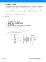
Read/Write IDIC e5551 The read/write Atmel IDIC e5551 is part of the transponder Atmel ATA5551M-PPMY. The data are transmitted bidirectionally between the base station and the transponder. The transponder receives power via a single coil from the RF signal generated by the base station. The single coil is connected to the chip and also serves as the IC’s bi-directional communication interface. Data are transmitted by modulating the amplitude of the RF signal. Reading of register contents occurs by damping the coil by an internal load. Writing into registers occurs by interrupting the RF field...
Open the catalog to page 3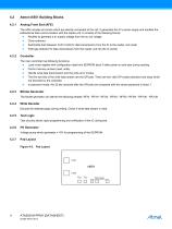
Atmel e5551 Building Blocks Analog Front End (AFE) The AFE includes all circuits which are directly connected to the coil. It generates the IC’s power supply and handles the bidirectional data communication with the reader unit. It consists of the following blocks: ● Rectifier to generate a dc supply voltage from the ac coil voltage Clock extractor Switchable load between Coil1/ Coil2 for data transmission from the IC to the reader unit (read) Field gap detector for data transmission from the reader unit into the IC (write) Controller The main controller has following functions: ● Load mode register...
Open the catalog to page 4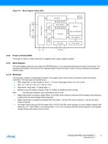
Figure 4-3. Block Diagram Atmel e5551 Write Decoder Mode Register Memory (264-bit EEPROM) Controller Bitrate Generator Analog Frontend Input Register Test Logic Test Pads Power-on Reset (POR) The power-on reset is a delay reset which is triggered when supply voltage is applied. Mode Register The mode register stores the mode data from EEPROM block 0. It is continually refreshed at the start of every block. This increases the reliability of the device (if the originally loaded mode information is false, it will be corrected by subsequent refresh cycles). 4.2.10 Modulator The modulator consists...
Open the catalog to page 5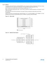
4.2.11 Memory The memory of the Atmel® e5551 is a 264 bit EEPROM, which is arranged in 8 blocks of 33 bits each. All 33 bits of a block, including the lock bit, are programmed simultaneously. The programming voltage is generated on-chip. Block 0 contains the mode data, which are not normally transmitted (see Figure 4-5). Block 1 to 6 are freely programmable. Block 7 may be used as a password. If password protection is not required, it may be used for user data. Bit 0 of every block is the lock bit for that block. Once locked, the block (including the lockbit itself) cannot be fieldreprogrammed....
Open the catalog to page 6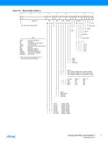
Figure 4-6. Memory Map of Block 0 [2] [1] [0] lock bit (never transmitted) *useSTOP useBT useST usePWD Key: AOR BT ST PWD STOP BR MS1 MS2 PSKCF MAXBLK reserved send Blocks: Anwer-On-Request use Block use Sequence Terminator use Password obey stop header (active low!) Bit Rate Modulator Stage 1 Modulator Stage 2 PSK Clock Frequency see Maxblock feature do not use * Bit 15 and 24 must always be at ”0”, otherwise malfunction appear. direct psk1 (phase change when input changes) psk2 (phase change on bit clk if input high) psk3 (phase change on rising edge of input) direct Manchester Biphase reserved...
Open the catalog to page 7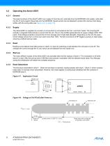
General The basic functions of the Atmel® e5551 are: supply IC from the coil, read data from the EEPROM to the reader, write data into the IC and program these data into the EEPROM. Several errors can be detected to protect the memory from being written with the wrong data (see Figure 4-21 on page 15). Supply The Atmel e5551 is supplied via a tuned LC circuit which is connected to the Coil 1 and Coil 2 pads. The incoming RF (actually a magnetic field) induces a current into the coil. The on-chip rectifier generates the dc supply voltage (VDD, VSS pads). Overvoltage protection prevents the IC...
Open the catalog to page 8
Figure 4-9. Terminators Bit Period Block Terminator Data Bit ”1” Sequence Terminator Data Bit ”1” VCoil 1 - Coil2 Waveform for Different Modulations Terminator not suitable for Biphase Modulation Figure 4-10. Read Data Streams and Terminators ST Sequence Terminator Block 2 Block Terminator Figure 4-11. MAXBLK Examples MAXBLK = 5 Loading Block 0 MAXBLK = 2
Open the catalog to page 9
Maxblock Feature If it is not necessary to read all user data blocks; the MAXBLK field in block 0 can be used to limit the number of blocks read. For example, if MAXBLK = 5, the Atmel® e5551 repeatedly reads and transmits only blocks 1 to 5 (see Figure 4-10 on page 9). If MAXBLK is set to ‘0’, block 0 – which is normally not transmitted – can be read. Terminators The terminators are (optionally selectable) special damping patterns, which may be used to synchronize the reader. There are two types available; a block terminator which precedes every block, and a sequence terminator which always follows...
Open the catalog to page 10All Atmel catalogs and technical brochures
 32-bit Microcontrollers
20 Pages
 MCUs Driving Displays
12 Pages
 Touch and 3D Gesture Control
12 Pages
 16-bit MCUs and DSCs
20 Pages
 XLP PIC® MCUs
8 Pages
 8-bit MCUs
16 Pages
 AT93C56B/66B Automotive
17 Pages
 Atmel AT86RF215 Device Family
235 Pages
 AT24C01C/02C
22 Pages
 maXTouch U Series - Flyer
2 Pages


Archived catalogs
 tinyAVR ATtiny24/44/84 Preliminary
240 Pages
 ATmega164P/324P/644P Preliminary
440 Pages
 ATmega48P/88P/168P/328P Preliminary
426 Pages
 ATmega1284P Preliminary
356 Pages
 AT90PWM216/316
359 Pages
 AT90PWM2, AT90PWM3, AT90PWM2B, AT90PWM3B
361 Pages
 ATmega329/3290/649/6490 Preliminary
392 Pages
 ATmega329P/3290P Preliminary
388 Pages
 AT90CAN32/64/128
428 Pages
 AT86RF230 Preliminary
98 Pages
 ATmega48/88/168 Automotive
335 Pages
 ATtiny25, ATtiny45, ATtiny85 Automotive
192 Pages
 ATtiny24/44/84 Automotive Preliminary
225 Pages
 AT86RF231 Preliminary
180 Pages
 Biometrics (Fingerprint Sensor)
20 Pages


- Transceiver module
- Potentiometer
- Industrial converter
- Ethernet transceiver
- Analog potentiometer
- Low-noise amplifier
- Microcontroller
- Analog amplifier
- Analog converter
- Circuit board
- Operational amplifier
- 32-bit microcontroller
- Low-power microcontroller
- Analog microcontroller
- High-speed converter
- General purpose microcontroller
- DAC converter
- Communication microcontroller
- High-speed amplifier
- ARM microcontroller